TM 9-2320-266-34
CHAPTER 19
REPAIR OF THE REAR DIFFERENTIAL ASSEMBLY
19-1. Servicing the Differential.
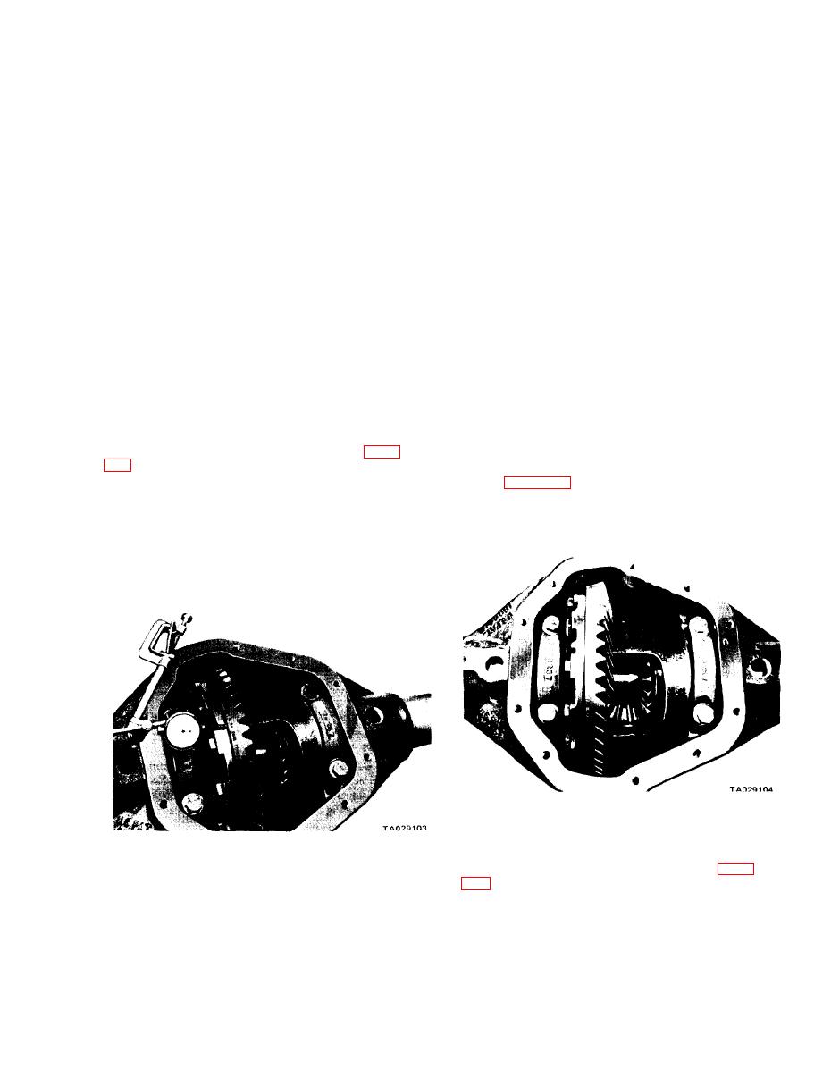
(6) Measure the drive gear back face runout by
a. Removal and Disassembly.
rotating the drive gear several complete revolutions and
reading the dial indicator. Mark the drive gear and differen-
(1) Remove the axle shaft (see TM 9-2320-266-20).
tial case at the point of maximum runout. (The markings
(2) Position the carrier and tube assembly in a vise
will be very helpful later in checking the differential case
or a suitable holding device with the carrier cover facing
runout). If the total indicator readings are above 0.006
upward. Thoroughly clean the outer area of the carrier and
inch, it may mean a loose drive gear or a damaged differen-
tube with cleaning solvent. Blow dry with compressed air.
tial case.
(3) Loosen and remove the cover screws and remove
(7) Check the clearance between the differential
the carrier cover. Tilt the assembly and drain the lubricant
bearing cap and the bearing cup by trying to insert a
into a container.
0.003 inch feeler gage between them. A 0.003-inch
(4) Use a cleaning solvent to wash and clean the
feeler gage should not be able to enter between the bearing
differential, bearings, gear ring and pinion, and internal
cap and the cup. If it does, the bearing cup may have
surfaces. Blow them dry with compressed air.
turned in the carrier, causing excessive wear.
(8) Note the identifying letters stamped on the
bearing caps and the face of the carrier housing seal
indicator stem slightly with the plunger at right angles to
surface (figure 19-2). Letters stamped on the left side are
the back face of the drive gear.
in a horizontal position while those on the right side are in
a vertical position. Always match the identifying letters
NOTE
for proper reassembly.
If side play was found during inspection,
runout can't be measured accurately.
Adjust the side play.
Figure 19-2. Bearing Cup Identification.
(9) Loosen and remove the differential bearing caps
and locate spreader tool W-129-A with the tool dowel pins
Figure 19-1. Measuring Drive Gear Runout.
seated in the locating holes of the axle housing (figure
19-1


