TM 9-2320-266-34
Table 18-3. Thrust Washer Wear Limits
Reaction shaft support to
front clutch retainer. . . . . . . . . . . . . . . . . . . . . . #1 Selective
0.061" to 0.063"
Natural
0.084" to 0.086" Red
0.102" to 0.104"
Yellow
Front clutch to rear clutch. . . . . . .
#2 0.061" to 0.063"
Input shaft to output shaft. . . . . . .
#3 0.063" to 0.064"
Front annulus support to
front carrier. . . . . . . . . . . . . .
#4 0.060" to 0.062"
Front annulus support to
driving shell. . . . . . . . . . . . . . #5 0.060" to 0.062"
Driving shell thrust plate. . . . . . .
#6 0.034" to 0.036"
Rear carrier to driving shell. . . . . .
#7 0.060" to 0.062"
Rear annulus thrust plate. . . . . . . . #8 0.034" to 0.036"
the shaft and in the annulus gear, making sure the teeth are
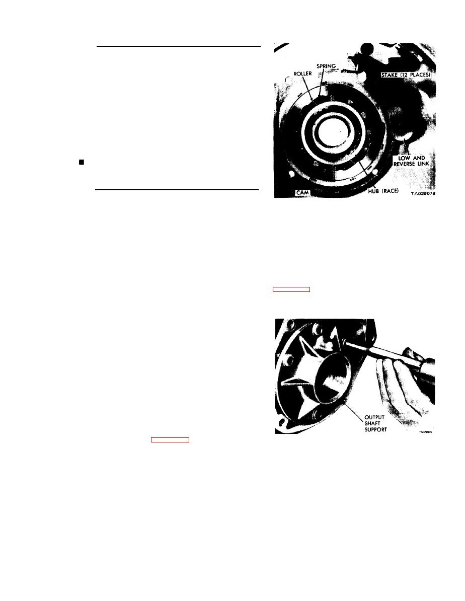
Figure 18-24. Overrunning Clutch, Low and
over the shaft splines.
Reverse Band Link.
(2) Position the rear planetary gear assembly in the
b. Replacing the Overrunning Clutch Cam. If the over-
rear annulus gear. Place the thrust washer on the front side
running clutch cam and/or roller spring retainer are found
of the planetary gear assembly.
damagcd, replace the cam and spring retainer as follows.
(3) Install a snap ring in the front groove of the sun
gear (long end of the gear). Insert the sun gear through the
(1) Remove the set screw from the case below the
front side of the driving shell. lnstall the rear steel washer
clutch cam.
and snap ring.
(2) Remove the four bolts securing the output shaft
(4) Carefully slide the driving shell and sun gear
support to the rear of the transmission case. Insert a punch
assembly onto the output shaft, engaging the sun gear teeth
through the bolt holes and drive the cam from the case
with the rear planetary pinion teeth. Place the thrust washer
inside the front driving shell.
another so the cam wiII be driven evenly from the case.
(5) Place a thrust washer on the rear hub of the front
planetary gear set. Slide the assembly into the front annulus
gear.
(6) Carefully work the front planetary and annulus
gear assembly on the output shaft, meshing the planetary
pinions with the sun gear teeth.
(7) With all components properly positioned, install
the selective snap ring on the front end of the output shaft.
Remeasure the end play of the assembly.
NOTE
The clearance can be adjusted by using
snap rings of various thicknesses. They
are available in 0.048, 0.055, and 0.062
inch thicknesses.
18-12. Overrunning Clutch.
Figure 18-25. Removing Overrunning Clutch Cam.
for smooth, round surfaces. They must be free of flat spots
and chipped edges. Inspect the roller contacting surfaces in
the cam and race for damage. lnspect the roller springs for
distortion, wear, or other damage. Inspect the cam setscrew
for tightness. If loose, tighten and restake the case around
the screw.
Change 2
18-13


