TM 9-2320-266-34
a fiber mallet, tap the drive gear loose from the differential
(10) Install the pilot stud on the left side of the axle
case pilot and remove it.
housing. Attach the dial indicator and load the indicator
(14) If the drive gear runout was over 0.006 inch in
stem slightly against the opposite side of the axle housing
step 5, remeasure the differential case flange runout. Install
the differential case with its respective bearing cups in the
axle housing. Loosen the spreader tool nut and remove it.
Install the bearing caps and tighten them snugly. Install the
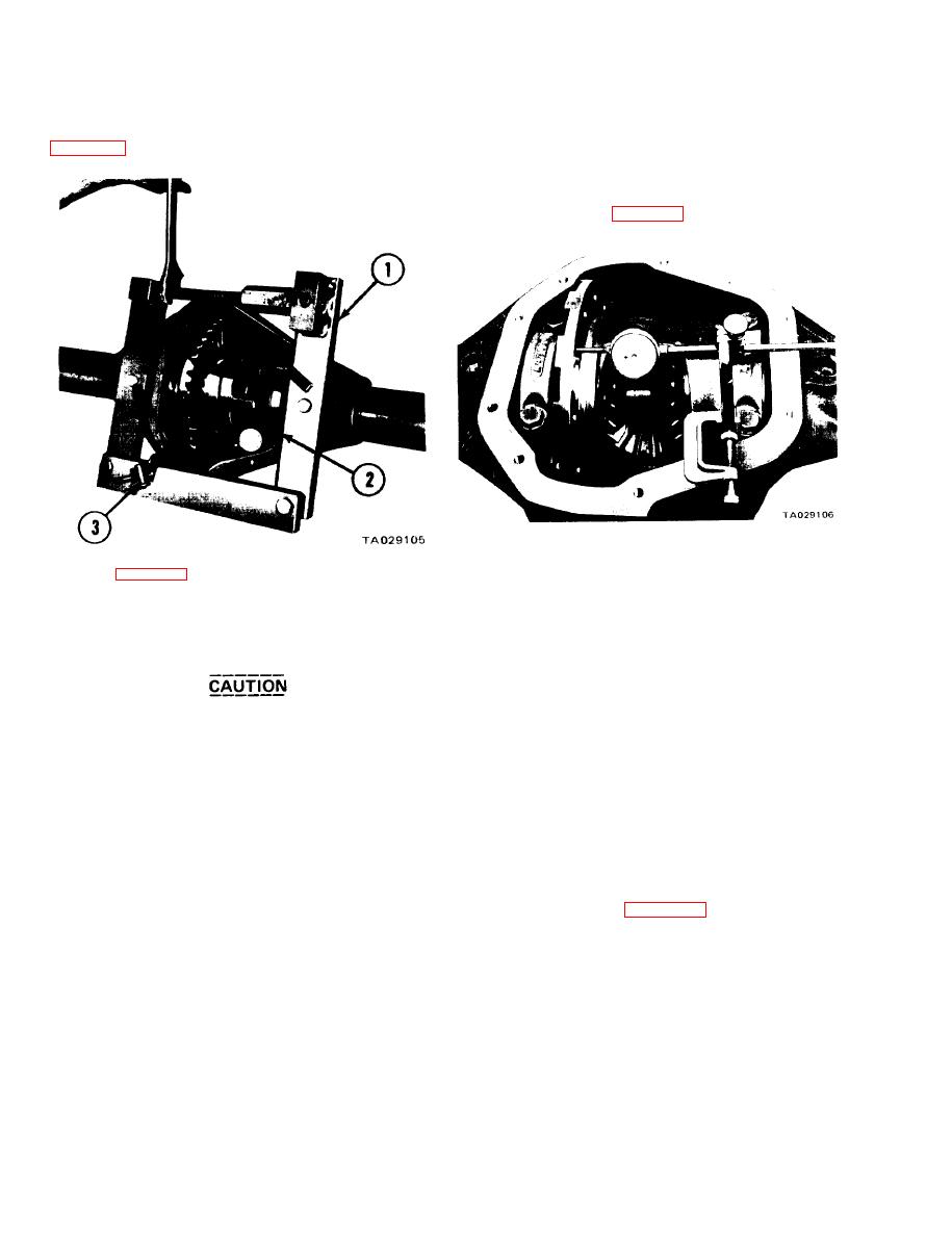
dial indicator as shown in figure 19-4, and measure the run-
out as described in step 5.
Figure 19-4. Measuring Differential Case Drive Gear
Mounting Flange Face Runout.
Legend for Figure 19-3:
(15) The total allowable runout is 0.003 inch. If runout
1. Spreader W-129-A
is excessive, try positioning the drive gear 180 degrees from
2. Dial indicator and pointer
the point of maximum runout when reassembling the ring
3. Dial indicator clamp
gear on the differential case. Repeat steps 8, 9, 10, and 11
Figure 19-3. Spreading Rear Axle Housing.
above, to see if runout is now 0.003 inch or less.
(16) Position the carrier and tube assembly in the vise
with the nose of the carrier in an upward position. Remove
Do not spread the housing over 0.020 inch,
the drive pinion nut and washer. Using a puller and holding
as it will result in permanent damage to the
tool C-3281, remove the drive pinion flange.
carrier casting.
(17) Using tool C-748, remove the drive pinion oil
(11) Tighten the spreader tool nut until you get a
seal. Remove the slinger, gasket, front pinion bearing cone
0.015-inch movement of the dial indicator, allowing you
and preload shim pack. Record the thickness of the shims in
to remove the differential case and ring assembly. Press
case they should be lost.
down on the opposite side of the spreader while applying
(18) Position the carrier and tube assembly on an
torque; this prevents the tool from popping off.
arbor press. Press out the drive pinion stem and the rear
(12) Remove the dial indicator and the differential
bearing cone assembly.
case and ring gear assembly from the axle housing. A light
(19) Using tool W-100-44-60, remove the front and
prying action with a screwdriver or pinch bar will loosen
rear pinion bearing cup (figures 19-5 and 19-6). Remove
the assembly for easy removal. Pry the differential case and
and record the thickness of the shim pack from behind the
ring gear as straight up as possible using leverage against the
rear pinion bearing cup.
differential case and carrier to prevent damage. Keep the
respective bearing cones if they are not worn or damaged,
and are to be reused.
(13) Place the differential case between the soft jaws
of a vise and remove and discard the drive gear screws. Using
19-2


