TM 9-2320-266-34
TA029457
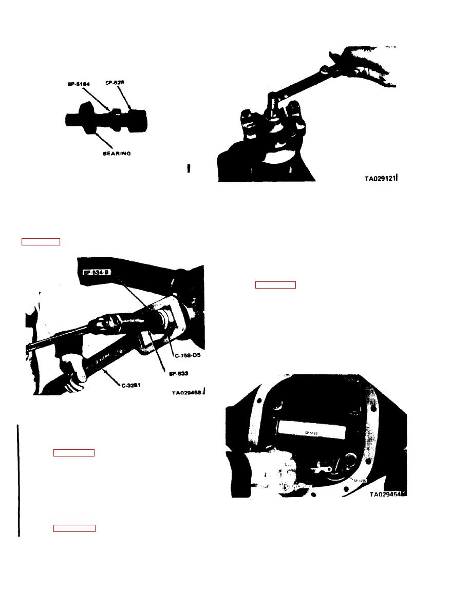
Figure 19-16. Checking Pinion Bearing Preload.
Figure 19-14. Installing the Rear Pinion Bearing Cone.
b. Determining Depth of Mesh and Preload.
(3) Position the tool and rear bearing in the axle
I
housing.
(1) With pinion tool SP-526 in place, attach adapter
SP-3250 with a cap screw and tighten securely.
(4) lnstall the front bearing cone and adapters
SP-534-B, SP-534, and SP-533 on tool SP-526 as shown in
(2) Center adapter SP-5183 in the axle housing.
bolts to 10 ft-lbs.
(4) Use a feeler gage to select the proper thickness
of shims that will fit snugly between adaptors SP-5183 and
SP-3250 (figure 19-17).
NOTE
This measurement will determine the cor-
rect thickness shim pack for installation
behind the rear pinion bearing cup and
the carrier casting.
Figure 19-15. Seating Bearing Cups in Axle Housing.
(5) Lubricate the drive pinion bearing cones.
(6) Hold the compression sleeve with tool C-328 and
tighten the compression nut until the cups are seated.
Refer to figure 19-15, above.
NOTE
Turn the tool several times while tighten-
ing, so the bearing rollers will aline in the
cups and prevent damage.
Figure 19-17. Determining Shim Pack Thickness for
pression nut. Retighten the nut to produce 10-30 in-lbs of
Drive Pinion Depth of Mesh.
preload (figure 19-16).
19-6
Change 1


