TM 9-2320-266-34
fit. Position the drive gear on the differential case pilot.
alining the threaded holes of the drive gear with hose in the
differential case flange.
(2) Insert new drive gear screws through the case
flange and into the drive gear. After all capscrews are
properly started, tap the drive gear against the differential
case flange with a non-metallic mallet.
(3) Clamp the unit between the brass jaws of a vise
and alternately tighten each capscrew to 110-115 ft-lbs.
(4) Position each differential bearing cone on the hub
of the differential case (without shims), with the small end
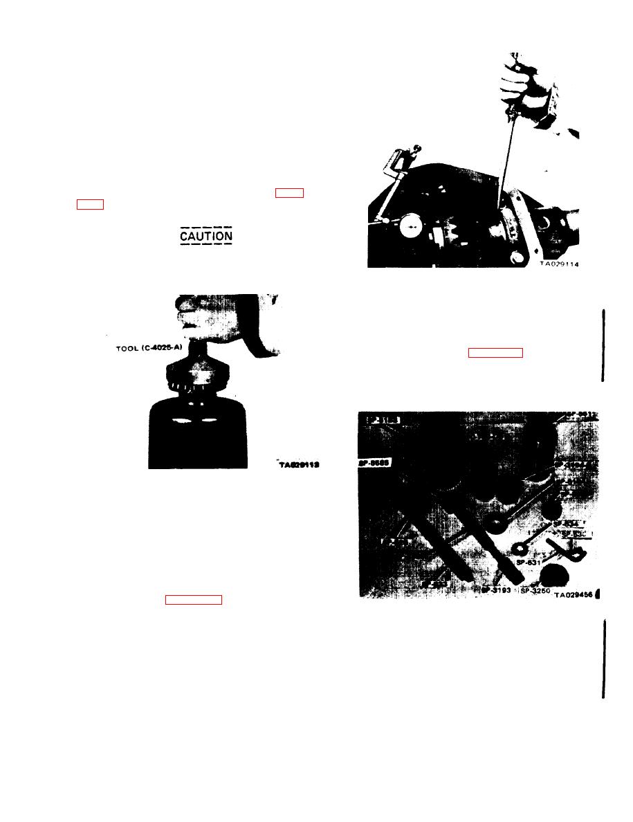
away from the drive gear, using tool C-4025-A (figure
the installing tool.
Never exert pressure against the bearing
cage, since this will damage the bearing
and make it unfit for further use.
Figure 19-12. Determining Shims to Obtain
"O" End Clearance.
19-2. Drive Pinion Depth of Mesh Setting and
Pinion Bearing Preload.
Use tool set C-758-44-60 (figure 19-13) to install the
drive pinion bearing cups, and to determine the pinion
depth of mesh as follows:
Figure 19-11. Installing Differential Bearing Cones.
(5) Position the differential bearing cups on their
respective cones and insert the differential case in the
carrier. Install the bearing caps in their correct positions.
Tighten the bearing cap bolts finger-tight.
(6) Install the dial indicator fixture with the indicator
pointer contacting the back face of the drive gear.
(7) Insert a screwdriver blade between the bearing cup
and housing, and pry the case assembly as far as possible to
one side of housing (figure 19-12). Set the dial indicator at
zero. Using a screwdriver, pry the case to the opposite side
Figure 19-13. Tool Set C-758-44-60.
of the housing and record the reading. This reading indicates
the amount of shims needed to take up the clearance
a. Installing Bearing Cups.
between the differential bearing cups and the case. The
(1) Position the drive pinion cups into the axle
shim pack thickness to be placed on the bearing hub
housing.
between the bearing cone and the differential case will be
(2) Install adapter SP-5184 on shaft SP-526. Then
calculated later in the procedure after you install the drive
install the rear pinion bearing cone (figure 19-14).
pinion and determine depth of mesh setting.
(8) Remove the dial indicator, loosen the bearing cap
bolts and remove the bearing caps. Remove the differential
assembly from the housing.
Change 1
19-5


