TM 9-2320-266-34
j. Extension Housing Long.
(3) Make sure the back-up light and neutral safety
switch
have been removed (paragraph 4-11).
(1) Install a snap ring in the front groove on the out-
put shaft. Install the bearing on the shaft with its outer
(4) Insert the parking lock rod through the opening
race ring groove toward the front. Press or tap the bearing
in the rear of the case with the knob positioned against
tight against the front snap ring, then install the rear snap
the reaction plug and sprag. Move the front end of the rod
ring.
toward the center of the transmission while pressing back
on the rod to force it past the sprag (rotate the output
(2) Place a new extension housing gasket on the
shaft if necessary).
transmission case. Position the output shaft bearing
retaining snap ring in the extension housing. Spread the
(5) Place the valve body mamual lever in the low
snap ring is far as possible, then carefully tap the extension
position. Place the valve body in its apprxoximate position
housing into place. Make sure the snap ring is fully
in the case. Connect the parking Iock rod to the manual
seated in the bearing groove.
lever and secure it with an "E" clip. Aline the valve body
in the case, and install the retaining bolts finger-tight.
(3) Install and tighten the extension housing bolts to
24 ft-lbs.
graph 4-11), place the manual valve in the neutral position.
(4) Install the basket and access plate on the side or
Shift the valve body if necessary to center the neutral
bottom of the extension housing mounting pad.
finger over the neutral switch plunger. Snug the bolts
(5) Install the speedometer pinion and the adapter
down evenly, then tighten them to 100 in-lbs.
assembly. Measure the input shaft end play, and correct it
(7) Install the gearshift lever and tighten the clamp
if necessary.
bolt. Check the lever shaft for binding in tile case by mov-
ing the lever through all detent positions. If binding exists,
I
k. Extension housing (4x4 Models).
loosen the valve body bolts and re-aline them.
(1) Position gasket.
(8) lnstall the flat washer and throttle lever. then
(2) Position the extension housing and bearing
tighten tile lever clamp bolt.
assembly.
(9) Adjust the kickdown and Iow-reverse bands.
(3) install the extension
housing-to-transmission
(10) Install the oil pan, using a new gasket. Tighten
bolts. Tighten to 24 ft-lbs.
the pan bolts to 150 in-lbs.
l. Valve Body Assembly and Accumulator Piston.
(1) Clean the mating surfaces and look for burrs
on both the transmission case amd the valve body steel
plate.
(2) Install the accumulator piston in the transmission
case. Place the piston spring on the accumulator piston
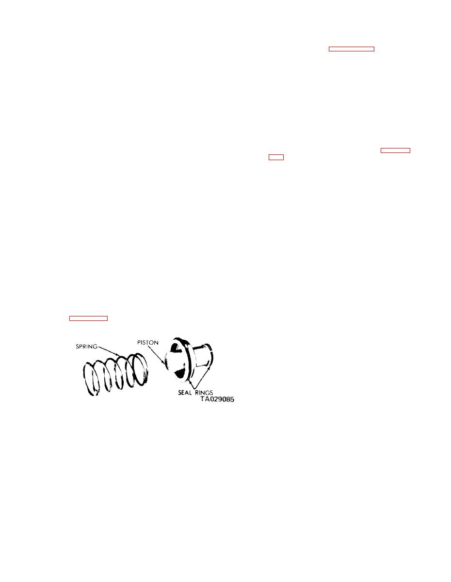
Figure 18-34. Accumulator Piston and Spring.
18-17/18-18 (blank)
Change 4


