TM 9-2320-266-34
NOTE
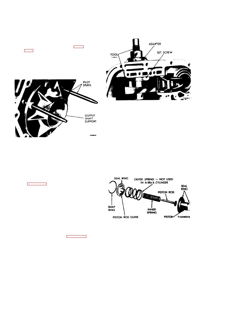
The output shaft support must be in the
case to install the overrunning clutch cam.
If the support requires replacement, drive
it back out of the case with a wood block
and hammer. To install, screw two
C-3283-A pilot studs into the case (figure
erably dry ice). Quickly position the sup-
port over the pilot studs, and drive it
firmly into the case with a wood block and
hammer.
Figure 18-27. Installing Overrunning Clutch Cam.
(1) Inspect the piston and guide seal rings for wear.
Make sure they turn freely in the grooves. Do not remove
the seal rings unless they are damaged.
(2) Check the piston for nicks, burrs, scores, or wear.
The piston plug must operate freely in the piston. Check the
piston bore for damage. Check the fit of the guide on the
piston rod, and check the piston spring for distortion.
Figure 18-26. Installing Output Shaft Support.
the bore in the piston and the "O" ring on the piston rod.
(3) Clean all burrs and chips from the cam area in the
(4) Check the band lining for wear. See if it is bonded
case.
to the band. Inspect the Iining for black burn marks, glazing,
(4) Place the spring retainer on the cam, making sure
non-uniform wear patterns, and flaking. If it is so worn that
the retainer lugs snap firmly into the notches.
grooves are not visible at the ends or in any portion of the
bands, replace the band. Replace hands that are distorted or
(5) Position the cam in the case with the cam serra-
have cracked ends.
tions alined with those in the case. Tap the cam evenly into
the case, as far as possible, with a soft mallet.
(6) Install tool C-3863-A with adapter SP-5124 as
shown in figure 18-27. Tighten the nut on the tool to seat
the cam into the case. Make sure it is firmly bottomed, then
install the cam retaining set screw. Stake the case around
the set screw to prevent it from coming loose.
(7) Remove the cam installing tool. Install and tighten
the support retaining screws to 140 in-lbs. Stake the case
around the cam in twelve places with a blunt chisel.
18.13. Kickdown Servo and Band.
a. Disassembly. Disassemble the "controlled load" servo
piston by removing the small snap ring from the servo piston.
Figure 18-28. Kickdown Servo (Front Band).
Then remove the washer, spring, and piston rod from the
servo piston.
depending upon which servo is being serviced.
18-14


