TM 9-2320-266-34
h. Oil Pump and Reaction Shaft Support. If it was diffi-
reverse drum slots. Be very careful not to damage the ground
cult to remove the pump assembly due to an exceptionally
surfaces on the output shaft during installation.
tight fit in the case, you may need to expand the case with
f. Front and Rear Clutch Assemblies. The front and rear
heat when installing the pump. Using a suitable heat lamp.
clutches, front band, oil pump, and reaction shaft support are
heat the case around the pump for a few minutes prior to
more easily installed with the transmission in an upright
installing the pump and the reaction shaft support assembly.
position. One method to support the transmission is out-
If the input shaft end play was not within specifications
lined in steps (1) and (2), below.
(0.036 to 0.082 inch) when measured before disassembly,
(1) Cut a 3-1/2-inch diameter hole in a bench, in the
replace the thrust washer on the reaction shaft support hub
end of a small oil drum, or in a large wooden box strong
with one of the proper thickness (figure 18-9). Refer to
enough to support the transmission. Cut or file the notches
thrust washer number 1 in table 18-3 for sizes available.
at the edge of the hole so the output shaft support will lay
(1) Screw two pilot studs into the pump opening in
flat in the hole.
the case (figure 18-33). Install a new gasket over the pilot
(2) Carefully insert the output shaft into the hole to
studs.
support the transmission upright, with its weight resting on
the flange of the output shaft support.
(3) Apply a coat of grease on the input to output
shaft thrust washer (figures 18-22 and 18-23), and install
the washer on the front end of the output shaft.
(4) Aline the front clutch plate inner splines, and
place the assembly in positron on the rear clutch. Make sure
the front clutch plate splines are fully engaged on the rear
clutch splines.
(5) Aline the rear clutch plate inner splines. grasp the
input shaft, and lower the two clutch assemblies into the
transmission case.
(6) Carefully work the clutch assemblies in a circular
motion to engage the rear clutch splines over the splints of
the front annulus gear. Make sure the front clutch drive lugs
are fully engaged in the slots in the driving shell.
of the kickdown band assembly. Assemble as follows:
(1) Slide the band over the front clutch assembly
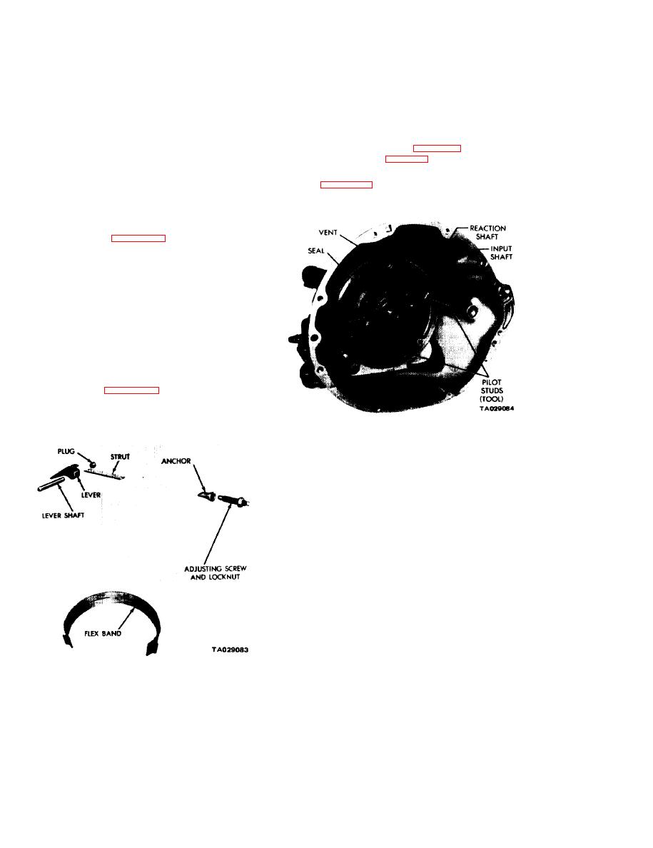
Figure 18-33. Installing Pump and Reaction Shaft
(2) Install the band strut, and screw in the adjuster
Support Assembly.
just enough to anchor the strut in place.
(2) Place a new rubber seal ring in the groove on the
outer flange of the pump housing. Make sure the seal ring is
not twisted. Coat it with grease for easy installation.
(3) Install the pump assembly in the case. Tap it
lightly with a soft mallet, if necessary. Install four pump
body bolts. Remove the pilot studs, and install the re-
maining bolts snugly and evenly.
(4) Rotate the input and output shafts to see if any
binding exists, then tighten the bolts to 175 in-lbs. Check
the shafts again for free rotation. Adjust both bands.
i.
Governor
and
Support.
(1) Position the support and governor body assembly
on the output shaft. Aline the assembly so the governor
shaft bole in the governor body alines with the hole m the
output shaft. Then slide the assembly into place. Install the
snap ring behind the governor body, Tighten the body-to-
support bolts to 100 in-lbs. Bend the ends of the lock straps
against the bolt heads.
(2) Place the governor valve on the valve shaft. Insert
Figure 18-32. Kickdown Band and Linkage.
the assembly into the body and through the governor weights
install tile valve shaft retaining snap ring.
18-16


