TM 9-2320-266-34
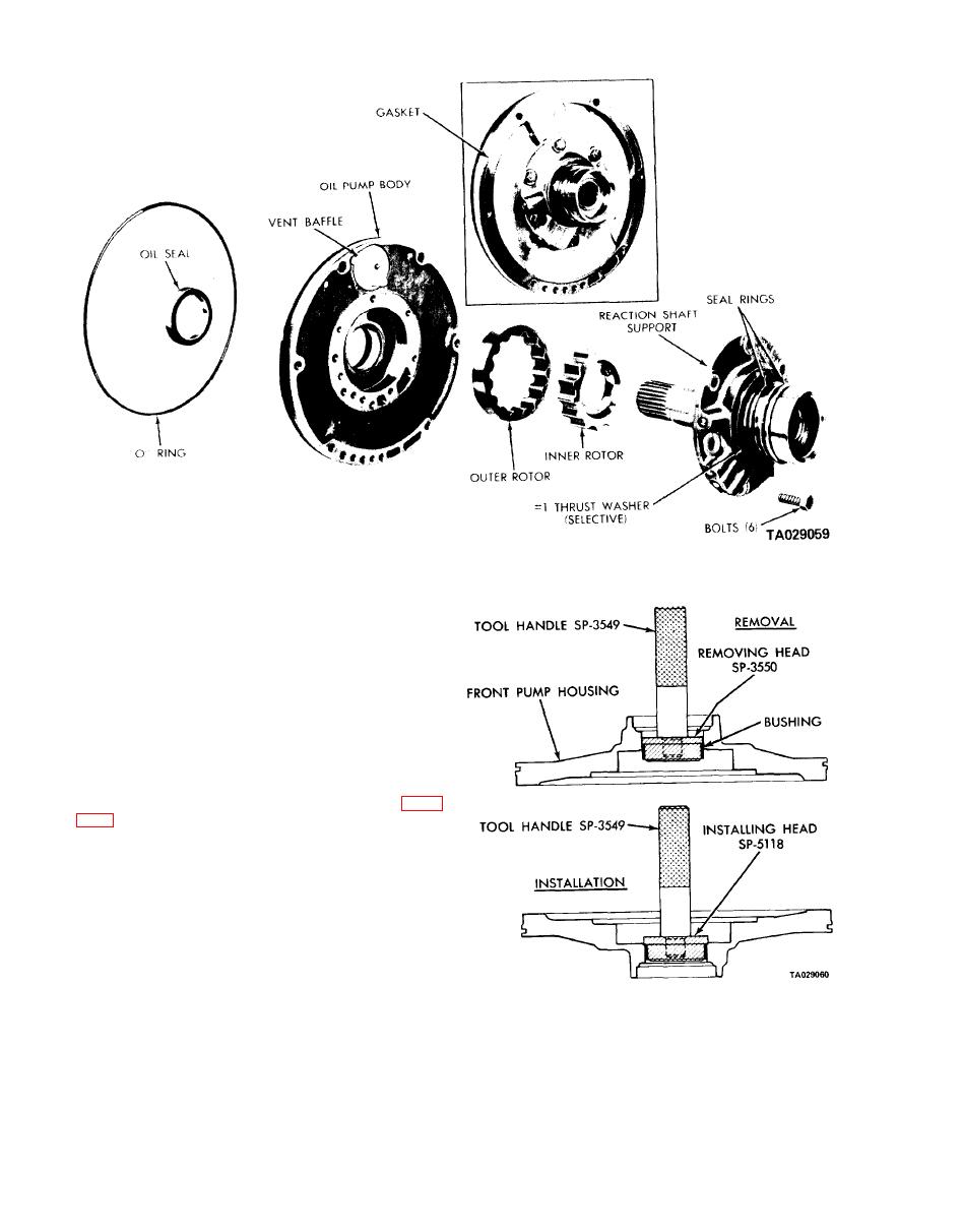
Figure 18-8. Oil Pump and Reaction Shaft Support.
(6) Measure the clearance between the inner and outer
teeth and the rotor tip. Clearances between 0.005 and 0.010
inch are satisfactory.
(7) Measure the clearance between the outer rotor and
its bore in the oil pump body. Clearances between 0.004
and 0.008 inch are satisfactory.
c. Replacing the Pump Bushing.
(1) Place the pump housing on a clean, smooth surface,
with the rotor cavity down.
(2) Place removing head tool SP-3550 in the bushing,
and install handle tool C-4171 in the removing head (figure
(3) Drive the bushing straight down and out of the
bore. Be careful not to cock the tool in the bore.
(4) Position a new bushing on installing head tool
SP-5118.
(5) With the pump housing on a smooth clean surface
(hub end down), start the bushing and installing head into
the bushing bore. Install handle tool C4171 in the installing
head.
(6) Drive the bushing into the housing until the tool
Figure 18-9. Replacing Pump Bushing.
bottoms in the pump cavity. Be careful not to cock the tool
during installation.
18-6


