TM 9-2320-266-34
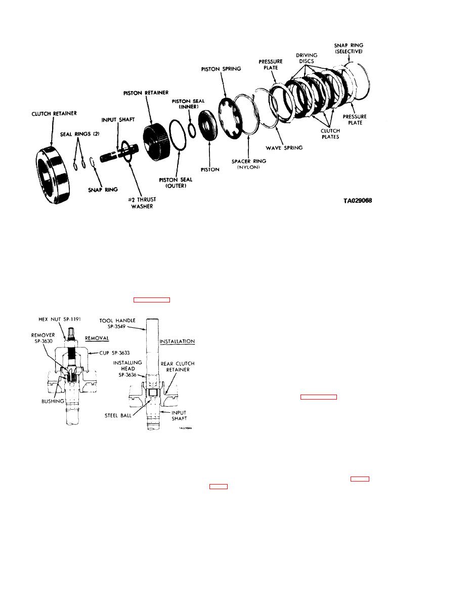
Figure 18-17. Rear Clutch.
(5) Turn the hex nut down against the cup to pull the
(10) Check for wear at the rear-clutch-to-front-clutch
bushing from the input shaft.
washer. If the washer is not 0.061 to 0.063 inch thick, re-
place it.
(6) Thoroughly clean the input shaft to remove any
chips made by the remover threads. Make certain the small
c. Replacing the lnput Shaft Bushing.
lubrication hole next to the ball in the shaft end is not
(1) Clamp the input shaft in a vise that has soft jaws.
plugged with chips. Be sure no chips are lodged next to the
Be careful not to clamp onto the seal ring lands or bearing
steel ball.
journals.
(7) Slide a new bushing onto installing head tool SP-
(2) Assemble remover tool SP-3630, cup tool SP-3633,
3636 and start into the bore of the input shaft.
and hex nut tool SP-1191 as shown in figure 18-18.
(8) Stand the input shaft upright on a clean, smooth
surface and install handle tool C-4171 in the installing head.
Drive the bushing into the shaft until the tool bottoms.
(9) Thoroughly clean the input shaft and clutch pis-
ton retainer before assembly and installation.
d. Assembly.
(1) If removed, press the input shaft
into
the
clutch piston retainer and install the snap ring.
(2) Lubricate and install the inner and outer seal rings
on the clutch piston. Make sure the lips of the seals face to-
ward the head of the clutch retainer, and are properly seated
in the piston grooves as shown in figure 18-19.
(3) Place the piston assembly in the retainer and, with
a twisting motion, seat the piston in the bottom of the
retainer.
(4) Position the clutch retainer over the piston retainer
Figure 18-18. Replacing Input Shaft Bushing.
splines and support the assembly so the clutch retainer re-
mains in place.
(3) With the cup held firmly against the clutch piston
(5) Place the clutch pistonn spring and spacer ring on
retainer, thread the remover into the bushing as far as pos-
top of the piston in the clutch retainer. Make sure the spring
sible by hand.
and spacer ring are positioned in the retainer recess. Start
(4) Use a wrench to screw the remover into the bush-
one end of the wave spring into the retainer groove (figure
ing three to four additional turns, to firmly engage the
threads in the bushing.
Make sure it is fully seated in the groove.
18-10


