TM 9-2320-266-34
NOTE
o. Low and Reverse Servo (Rem).
Be careful not to lose the thrust washer
(1) Compress the low and reverse servo piston spring
located between the rear end of the input
using the engine valve spring compressor. Remove the snap
shaft and the forward end of the output
ring.
shaft.
(2) Remove the spring retainer, spring, and servo pis-
ton and plug assembly from the case.
k. Planetary Gear Assemblies, Sun Gear, and Driving Shell.
18-7. Reconditioning Subassemblies.
(1) While supporting the output shaft and driving shell,
carefully slide the assembly forward and out through the
a. The following procedures cover disassembly, inspec-
case.
tion, repair, and assembly of each subassembly as removed
from the transmission.
(2) Be very careful not to damage the ground surface
on the output shaft during removal.
b. Heli-Coil or equivalent inserts are recommended for
repairing damaged, stripped, or worn threads in aluminum
l. Rear Band and Low-Reverse Drum. Remove the low-
parts (see table 4-3).
reverse drum, then loosen the rear band adjuster and remove
the band strut and link. Remove the band from the case.
c. Pre-sized service bushings are available for replacement
for almost all bushings in the transmission. The two bushings
m. Overrunning Clutch.
in the sun gear are not serviced because of the low cost of the
(1) Before disassembly, note the position of the over-
sun gear assembly. If bushings are found worn or scored,
running clutch rollers and springs in order to position them
replace them as outlined in the following reconditioning
in reassembly.
procedures.
(2) Carefully slide out the clutch hub and remove the
d. Use of crocus cloth is permissible where necessary, pro-
rollers and springs. If the overrunning clutch cam and/or
vided it is used carefully. When used on valves, be extremely
roller spring retainer are found damaged or worn, refer to re-
careful to avoid rounding off the sharp edges. A sharp edge
placement procedures in paragraph 18-12.
is vitally important to this type of valve. They prevent dirt
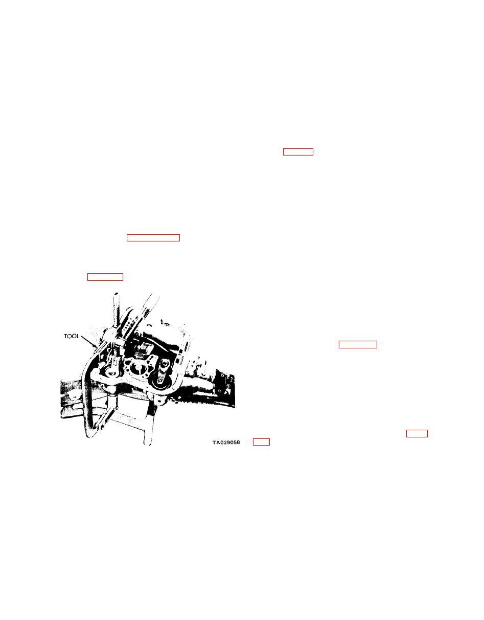
n. Kickdown Servo (Front).
and foreign matter from getting between the valve and body,
thus reducing the possibility of sticking. When it becomes
(1) Compress the kickdown servo spring by using an
necessary to recondition the transmission, and the truck has
engine valve spring compressor. Then remove the snap ring
accumulated considerable mileage, install new seal rings on
as shown in figure 18-7.
parts requiring their usage.
NOTE
Coat each part with automatic transmission
fluid during assembly.
18-8. Oil Pump and Reaction Shaft Support.
(1) Remove the bolts from the rear side of the reaction
shaft support and lift the reaction shaft support off the
pump.
(2) Remove the rubber seal ring from the pump body
flange.
(3) Drive out the oil seal with a blunt punch.
b. Inspection Procedure.
(1) Look for wear or broken locks on the interlocking
steel rings mounted on the reaction shaft support (figure
(2) Inspect all machined surfaces on the pump body
Figure 18-7. Compressing Kickdown Servo Spring.
and reaction shaft support for nicks and burrs.
(2) Remove the rod guide, springs, and piston rod from
(3) Look for wear or scores on the pump body and re-
the case. Be careful not to damage the piston rod or guide
action shaft support bearings.
during removal.
(4) Inspect the pump rotors for scoring or pitting.
(3) Withdraw the piston from the transmission case.
(5) Clean the rotors and install them in the pump
(4) Disassemble the "controlled load" servo piston
body. Then place a straightedge across the face of the rotors
assembly by removing the small snap ring from the servo
and pump body. Use a feeler gage to measure the clearance
piston. Then remove the washer, spring, and piston rod from
between the straightedge and the rotor faces. Clearances be-
the servo piston.
tween 0.0015 and 0.0030 inch are satisfactory.
18-5


