TM 9-2320-266-34
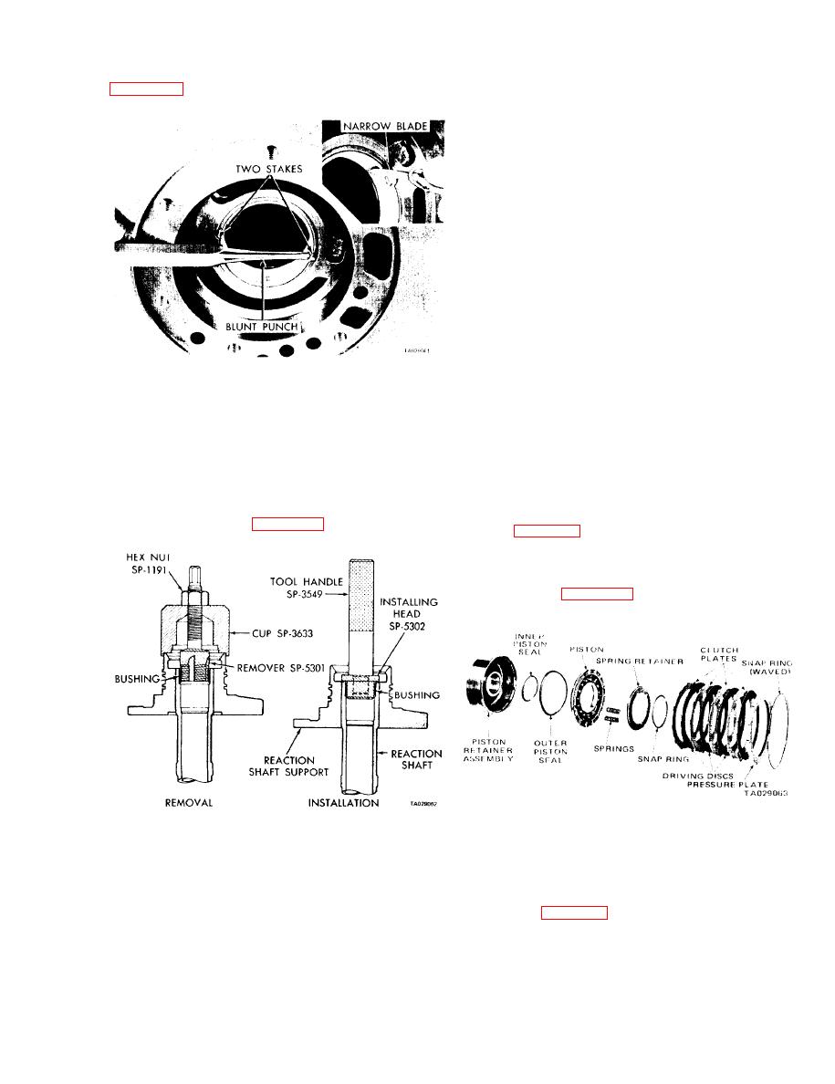
(7) Stake the bushing in place by using a blunt punch
(2) With the cup held firmly against the reaction shaft,
or similar tool, gently tapping at each stake slot location
thread the remover into the bushing as far as possible by
hand.
(3) Use a wrench to screw the remover into the bush-
ing three to four additional turns to firmly engage the
threads in the bushing.
(4) Turn the hex nut down against the cup to pull the
bushing from the reaction shaft. Thoroughly clean the re-
action shaft to remove any chips made by remover threads.
(5) Lightly grip the bushing in a vise or with pliers,
and back the tool out of the bushing. Be careful not to dam-
age threads on the bushing remover.
(6) Slide a new bushing (chamfered end first) onto in-
stalling head tool SP-5302, and start it into the bore of the
reaction shaft.
(7) Support the reaction shaft upright on a clean,
smooth surface and install handle tool C-4171 in-the instal-
ling head. Drive the bushing into the shaft until the tool
bottoms.
(8) Thoroughly clean the reaction shaft support assem-
Figure 18-10. Staking Pump Bushing.
bly before installation.
(8) Using a narrow-bladed knife or similar tool, remove
e. Assembling the Oil Pump and Reaction Shaft Support.
high points or burrs around the staked area. Do not use a file
(1) Assemble the pump rotors and "O" ring in the
or similar tool that will remove more metal than is necessary.
pump housing.
(9) Thoroughly clean the pump housing before
(2) Install the reaction shaft support. Install retaining
installation.
bolts and tighten them to 160 in-lbs.
d. Replacing the Reaction Shaft Bushing.
(3) Place a new oil seal in the opening of the pump
(1) Assembly remover tool SP-5301, cup tool SP-3633,
housing (lip of the seal facing inward), using tool C-3860 as
and hex nut tool SP-1191 (figure 18-11).
shown in figure 18-3. Drive the seal into the housing until
the tool bottoms.
18-9. Front Clutch.
of the front clutch assembly.
Figure 8-12. Front Clutch.
Figure 18-11. Replacing Reaction Shaft Bushing.
(1) Remove the large waved snap ring that secures the
pressure plate in the clutch piston retainer. Lift the pressure
plate and clutch plates out of the retainer.
NOTE
Do not clamp any part of the reaction
spring retainer (figure 18-13). Compress the springs and re-
shaft or support in a vise.
move the snap ring. Then slowly release the tool until the
spring retainer is free of the hub. Remove the tool, retainer,
and springs.
18-7


