TM 9-2320-266-34
c. Oil Pan.
snap ring spread as far as possible, carefully tap the extension
housing off the output shaft and bearing.
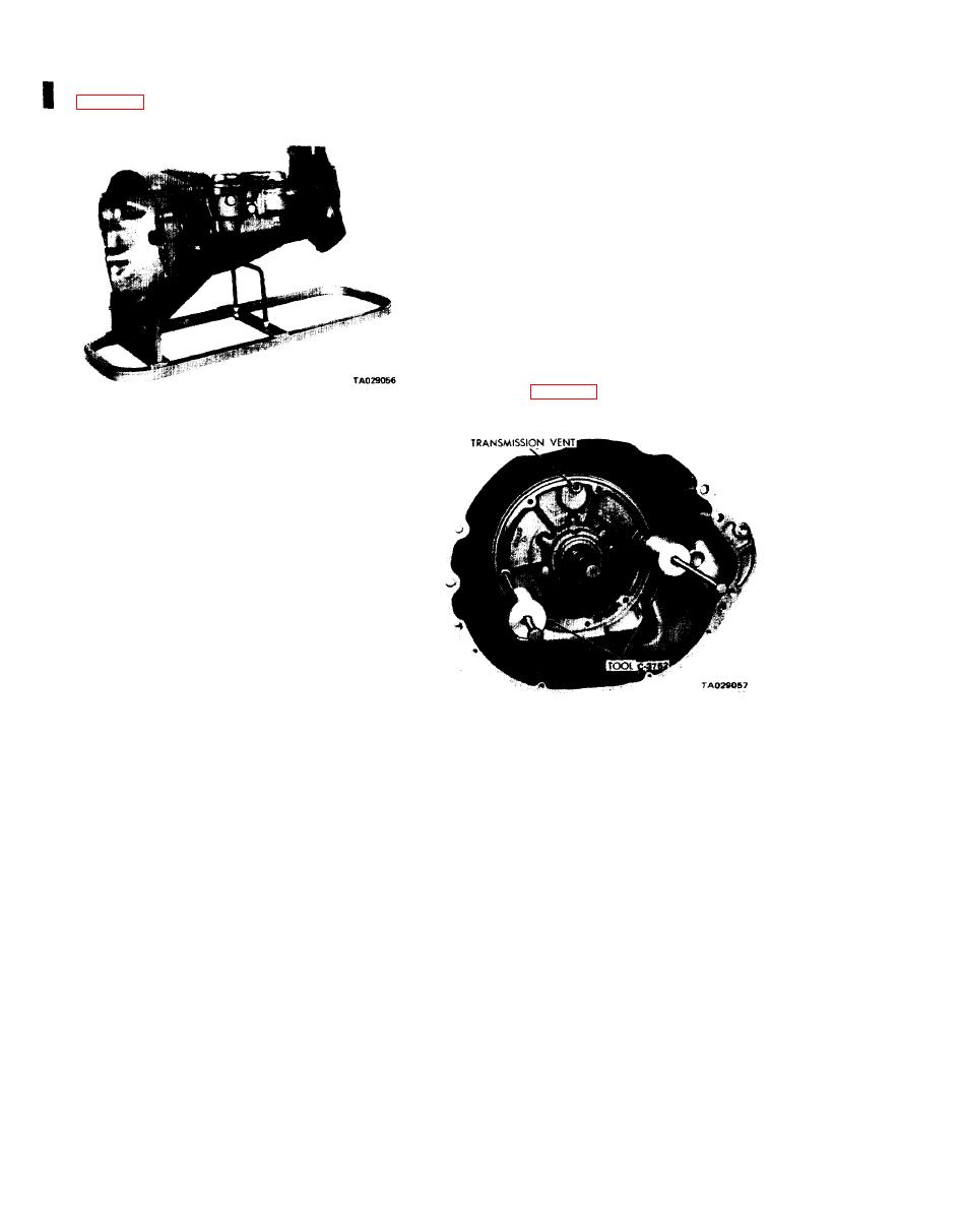
(1) Place the transmission assembly in a repair stand
(4) Using heavy duty snap ring pliers, remove the out
put shaft bearing rear snap ring. Remove the bearing from
the shaft. Remove the front snap ring.
g. Governor and Support.
(1) Carefully pry the small snap ring from the weight
end of the governor valve shaft. Slide the valve and shaft
assembly out of the governor body.
(2) Remove the snap ring from behind the governor
body. Then slide the governor body and support assembly
off the output shaft.
h. Oil Pump and Reaction Shaft Support.
(1) Tighten the front band adjusting screw until the
band is tight on the front clutch retainer. This prevents the
clutch retainer from coming out with the pump, which might
cause unnecessary damage to the clutches.
(2) Remove the oil pump housing retaining bolts.
(3) Using puller set C-3752, remove the pump housing
flange as shown in figure 18-6.
Figure 18-5. Transmission Installed in Repair Stand.
(2) Unscrew the oil pan bolts and remove the oil pan
and gasket.
d. Valve Body Assembly.
(1) Loosen the clamp bolts and remove the throttle
and gearshift levers from the transmission.
(2) Remove the back-up light and neutral safety
switch.
(3) Remove the 10 valve-bud y-to-transmission bolts.
Remove the "E" clip securing the parking lock rod to the
valve body manual lever.
(4) While lifting the valve body upward out of the
transmission case, disconnect the parking lock rod from the
lever.
e. Accumulator Piston and Spring. Lift the spring off the
accumulator piston and withdraw the piston from the case.
f. Extension Housing and Output Shaft Bearing. Before
removing the extension housing. pull the parking lock rod
Figure 18-6. Removing Primp and Reaction Shaft
forward out of the case. Rotate the propeller shaft if neces-
Support Assembly.
sary to aline the parking gear and sprag. This will permit the
knob on the end of the control rod to pass the sprag. Then
(4) Evenly bump out the pump and reaction shaft
proceed as follows:
support assembly with two "knocker weights" and remove
them from the case.
(1) Remove the speedometer pinion and adapter
assembly.
i. Front Band and Front Clutch.
(2) On 4X4 models with short extension housing,
(1) Loosen the front band adjuster. remove the band
remove the extension housing-to-transmission bolts and tap
strut, and slide the band out of the case.
the housing lightly to break it loose. Remove the housing
(2) Slide the front clutch assembly out of the case.
and bearing assembly.
j. Input Shaft and Rear Clutch. Grasp the input shaft
(3) On 4X2 models with long extension housing, re-
and slide the shaft and rear clutch assembly out of the case.
move the extension housing-to-transmission bolts. Remove
the access plate and gasket from the bottom or side of the
extension housing mounting pad. Spread the large snap ring
from the output shaft bearing with snap pliers. With the
18-4
Change 2


