TM 9-2320-266-34
gear at intervals during the heating process. When the water
18-2. Starter Ring Gear Replacement.
is hot enough to just boil, the gear heating is complete.
The starter ring gear is mounted directly on the outer di-
c. Installation.
ameter of the torque converter front cover. Remove the
torque converter from the vehicle, and replace the gear as
(1) After the ring gear is expanded by heating, place
follows:
it in position on the converter front cover. Tap the gear
with a plastic or rawhide mallet until it is even with the
a Removal.
scribed line (made during removal) on the front cover.
(1) Cut through the weld material at the rear of the
Make sure the gear is even around the full circumference
ring gear with a hack saw or grinding wheel (figure 18-1). Be
of the front cover.
careful not to cut or grind into the front cover stamping.
cover. Be careful to place, as nearly as possible, the same
amount of weld material in exactly the same location as was
used in the original weld. This is necessary in order to main-
tain proper balance of the unit. Place the-welds alternately
on opposite sides of the converter to minimize distortion.
(3) Follow these rules when making the weld:
(a) Do not gas weld.
(b) Use a d.c. welder that is set at straight polarity,
or an a.c. welder if the proper electrode is available.
(c) Use a 1/8-inch diameter welding rod and a
welding current of 80 to 125 amps.
(d) Direct the arc at the intersection of the gear
and front cover at a 45 degree angle from the rear face of
the gear.
(4) Inspect the gear teeth and remove all nicks where
the metal is raised, or where there is weld metal splatter, etc.,
in order to insure quiet starter operation.
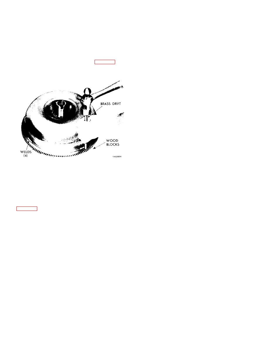
Figure 18-1. Removing Starter Ring Gear.
18-3. Torque Converter Flushing.
(2) Scribe a heavy line on the front cover next to the
a General. When a transmission failure has contaminated
front face of the ring gear to aid in locating the new gear.
flush the torque converter, oil coolers, and tubes.
the fluid,
(3) Support the converter with the front lug faces
This will insure that metal particles or sludged oil are not
resting on blocks of wood. The converter must not rest on
later transferred back into the reconditioned transmission.
the front cover hub during this operation. Using a blunt
b. Hand Flushing.
chisel or drift and hammer, tap down on the ring gear near
the welded areas to break any remaining weld material
(1) Place the converter in a horizontal position and
pour 2 quarts of new, clean solvent or kerosene into the
converter.
converter through the impeller hub.
(4) Smooth off the welded areas on the cover with a
(2) Turn and shake the converter to swirl the solvent
file.
through the internal parts. Turn the turbine and stator to
dislodge any foreign material, using the transmission input
b. Preparing for Installation. Any of the following meth-
and reaction shafts.
ods may be used to heat and expand the starter ring gear in
order to install it on the converter.
(3) Position the converter in its normal operating
position with the drain plug at the lowest point. Remove
(1) Oven. Place the ring gear in an oven and set the
the drain plug and drain the solvent. Rotate the turbine and
temperature at 200 F. Allow the ring gear to remain in the
stator and shake the converter while draining, to prevent
oven for 15 to 20 minutes.
dirt particles from settling.
(2) Boiling water. Place the ring gear in a shallow
(4) Repeat the flushing operation at least one more
container, add water, bring the water to a boil, and heat for
time, or as many times as required until the drained solvent
approximately 8 minutes.
or kerosene is clear.
(3) Steam. Place the ring gear on a flat surface and
(5) After flushing, shake and rotate the converter sev-
direct a steam flow around the gear for approximately 2
eral times with the drain plug out to remove any residual
minutes.
solvent and dirt. Flush any remaining solvent from the con-
(4) Flame. Place the ring gear squarely on a flat sur-
verter with 2 quarts of new transmission fluid. This will
face. Using a medium size tip, direct a slow flame evenly
prevent any adverse effect the solvent may have on the trans-
around the inner rim of the gear. Do not apply the flame to
mission seals. Reinstall the drain plug and tighten to
the gear teeth. Place a few drops of water on the face of the
90 in-lbs.
18-2


