TM 9-2320-266-34
(4) Remove the valves; tag them to insure installation
(c) Move the valve to and from the indicator. The
in their original location.
dial indicator reading should not exceed 0.017 inch. Ream
the guides for valves with oversize stems if the dial indicator
c. Inspecting the Valves.
reading is excessive.
(1) Clean the valves thoroughly and discard any burned,
warped, or cracked valves.
NOTE
(2) Measure the valve stems for wear. A new intake
Service valves with oversize stems are avail-
valve stem diameter should measure 0.372 to 0.373 inch and
able in 0.005, 0.015, and 0.030 inch over-
the exhaust valve stem diameter should measure 0.371 to
size. Reamer sizes to accommodate the
0.372 inch. If wear exceeds 0.002 inch, replace the valve.
oversize valve stem are set forth in table
11-3.
(3) Remove carbon and varnish deposits from the in-
side of the valve guides.
Table 11-3. Reamer Sizes
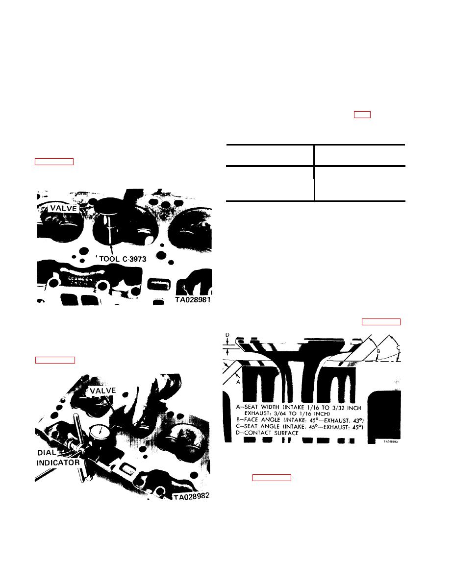
(4) Measure the valve stem guide clearance as follows:
Valve guide
Reamer
(a) Install sleeve tool C-3973 over the valve stem
size
oversize
the valve at the correct height for a dial indicator.
0.379-0.380 in
0.005 in
0.389-0.390 in
0.015 in
0.404-0.405 in
0.030 in
(d) Slowly turn the reamer by hand and clean the
guide thoroughly before installing a new valve.
NOTE
Do not attempt to ream the valve guides
from standard directly to 0.030 inch. If it
is necessary to go to 0.030 inch, use a
step procedure of 0.005, 0.015, and 0.030
inch so the valve guides may be reamed
true in relation to the valve seat.
d. Refacing Valves and Valve Seats.
a 45 degree angle. These angles are shown in figure 11-20.
Figure 11-18. Installing Valve and Tool C-3973.
(b) Attach a dial indicator to the cylinder head
and set it at a right angle to the valve stem being measured
Figure 11-20. Valve Face and Seat Angle.
(2) Inspect the remaining margin after the valves are
refaced (figure 11-21). Discard any valves with less than
3/64-inch margin.
Figure 11-19. Measuring Valve Guide Wear.
11-10


