TM 9-2320-266-34
e. Installing Piston Pins. The piston pin rotates in the
(9) Install the nut on the puller screw to hold the
piston only, and is retained only by the interference fit of
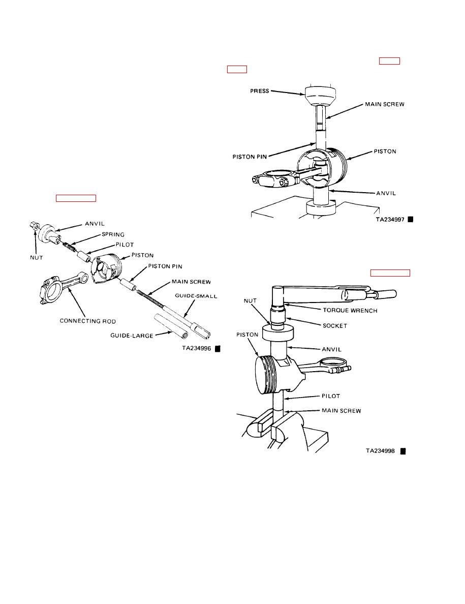
assembly together. Place the assembly on a press (figure
the piston pin in the connecting rod. No locks are used in
the piston to retain the piston pin. Tool C4158-L is required
to install the piston pin. The pilot tool C4200-3 and anvil
tool C4200-1 are also required, and are used with tool
C4158-L. Install the pin as follows:
(1) Test the piston pin fit in the piston prior to
assembling the piston `and connecting rod. The pin should
be a sliding fit in the piston. If a new pin fits loosely, the
piston and pin assembly must be replaced.
(2) Lubricate the pin holes in the piston and connect-
ing rod.
(3) Select the appropriate pilot and anvil for use with
tool C4158-L.
(4) Arrange tool C4158-L for installation of the pis-
ton pin (figure 11-12).
Figure 11-13. Installing Piston Pin with Tool C-4158-L.
(10) Press the piston pin in until the pin bottoms on
the pilot. This will position the pin in the connecting rod.
(11) To measure pin fit, remove the tool and arrange
tool parts and the piston assembly as shown in figure 11-14.
Figure 11-12. Arrangement of Tool C-4158-L for Installing
Piston Pin.
(5) Install the spring inside the pilot and install the
spring and pilot in the anvil. Install the piston pin over the
main screw.
(6) Place the piston, with the front up, over the pilot
so the pilot extends through the piston pin hole.
(7) Position the connecting rod over the pilot which
extends through the piston pin hole.
NOT E
Figure 11-14. Testing Piston Pin Fit in Connecting Rod.
Assemble the rods to the pistons of the
right cylinder bank (2, 4, 6, and 8) with the
indent on the piston head opposite the
to 15 ft-lbs. The connecting rod should not move. If it
large chamfer on the large bore end of the
moves, obtain a connecting rod with the proper small end
connecting rod. Assemble the rods to the
bore diameter and repeat the installation and tightening
pistons of the left cylinder bank (1, 3, 5,
procedure.
and 7) with the indent on the piston head
f. Fitting Rings.
on the same side as the large chamfer on
(1) Use an inverted piston to push the rings down to
the large bore end of the connecting rod.
insure positioning the rings squarely in the cylinder bore be-
fore measuring. Measure the piston ring gap when the ring
(8) Install the main screw and the piston pin in the
piston.
Change 7
11-8


