TM 9-2320-266-34
is about 2 inches from the bottom of the cylinder bore in
which it is to be fitted.
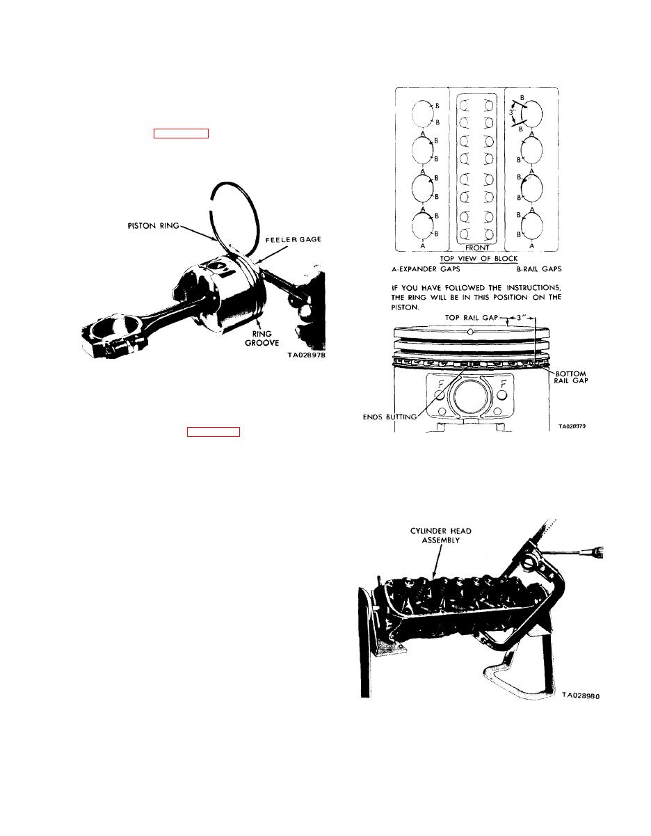
(2) Insert a feeler gage in the gap. The minimum ring
gap is 0.010 inch for compression rings and 0.015 inch for
oil ring steel rails.
(3) Measure the side clearance between the piston ring
and the ring land (figure 11-15). Clearance should be 0.0015
to 0.003 inch for the top compression ring and the intermedi-
ate ring. The oil ring steel rail should be free in the groove.
Figure 11-15. Measuring Piston Ring Side Clearance.
(4) Insert the keys on the spacer expander into the
hole in the oil ring groove (over the piston pin front boss).
Install the ring as shown in figure 11-16.
Figure 11-16. Proper Oil Ring Installation.
(5) Install the compression rings in the middle and top
grooves.
NOTE
Always look for the word "Top" marked
on one side of each compression ring. The
side marked "Top" must always face the
top of the piston when you install the ring.
11-8. Servicing the Cylinder Head Assemblies.
a. Measure for Flatness. Use a straightedge to measure the
cylinder head mating surfaces for flatness. Maximum allow-
able warpage is 0.009 inch per foot. Reface or replace cyl-
inder head assemblies that do not meet the specification.
b. Disassembly. Disassemble the cylinder heads as follows:
(1) Compress the valve springs using a valve spring
compressor (figure 11-17).
(2) Remove the valve retaining locks, spring retainers,
step cup, seals, and springs.
(3) Before removing the valves, remove any burrs from
the valve stem lock grooves to prevent damage to the valve
guide.
Figure 11- I 7. Compressing Valve Spring.
11-9


