TM 9-2320-266-34
(4) Install the wheel. Lower the vehicle and remove
the jack.
new bushings, be sure the control arm is supported
squarely at the point where the bushing is being pressed in.
(5) Adjust the caster and camber. Tighten the
Do not usc oil or grease to aid in installation.
eccentric pivot bolts to 70 ft-lbs.
7-7. Upper Ball Joint.
a. Removal.
for separating the upper ball Joint from the steering
knuckle.
(2) Using tool C-3561, loosen the ball joint retaining
nut, then remove the ball joint from the upper control arm.
b. Installation.
(1) Screw the new ball joint into the control arm as
far as possible by hand. Using tool C-3561, tighten the ball
joint to 125 ft-lbs. Be sure it is seated fully against the arm.
(2) Press the ball joint seal onto the upper ball joint.
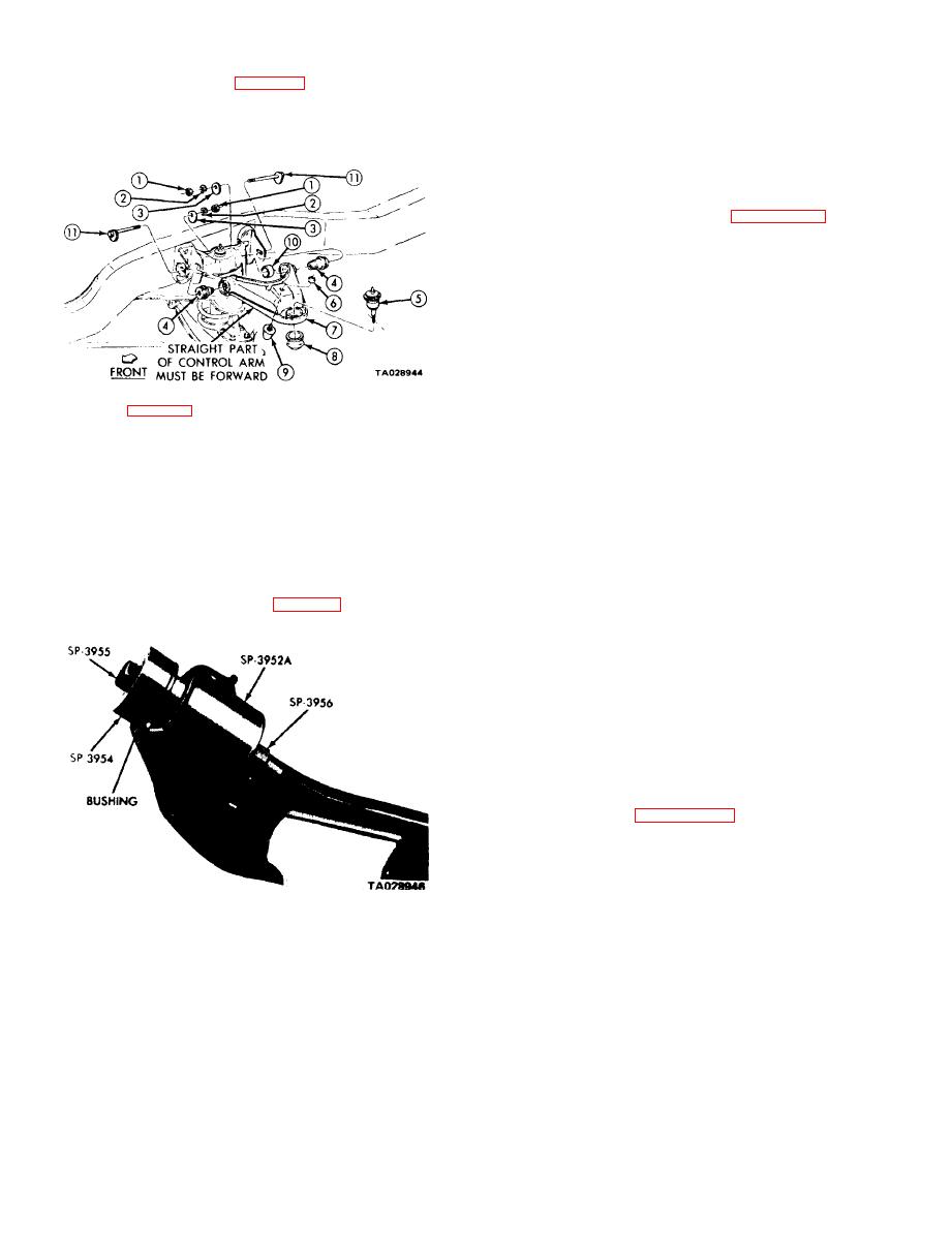
Legend for Figure 7-6:
(3) Insert the ball joint into the steering knuckle.
7. Upper control arm
1. Nut
Install the ball joint nut; tighten it to 135 ft-lbs. Install
8. Upper ball joint
2. Lockwasher
the cotter keys.
9. Bumper assembly
3. Cam
4. Bushing assembly
10. Sleeve
(4/ Install the wheel, lower the vehicle, and remove
5. Ball joint
11. Cam and bolt assembly
the jack stands.
6. Locknut
7-8. Steering Knuckle.
Figure 7-6. Upper Control Arm.
a. Removal.
(1) Position the flange end of the new bushing in
(1) Chock the rear wheels, raise the vehicle, and
tool C-3962. Support the control arm squarely, and press
remove the wheel.
the bushings into the control arm (from outside) until the
(2) Remove the caliper from the rotor. Secure the
tapered portion seats on the arm (figure 7-7).
caliper out of the way.
(3) Remove the grease cap, cotter key, nut, washer,
and outer bearing.
(4) Slide the rotor assembly from the steering
knuckle. Do not drag the seal or inner bearing over the
steering knuckle thread or the thread, bearing, and oil
seal may be damaged.
(5) Disconnect the tie rod at the steering knuckle
arm (see TM 9-2320-266-20).
(6) Separate the steering knuckle from the ball joints
following the procedure in paragraphs 7-3 and 7-6. Place
the assembly on a bench.
(7) Separate the components.
b. Installation.
(1) Position the seal on the steering knuckle. Install
Figure 7-7. Installing Upper Control Arm Bushing.
an adapter and tighten the mounting bolts to 100 ft-lbs.
(2) Position the control arm and install the eccentric
(2) Aline the steering knuckle arm to the steering
pivot bolts and nuts linger-tight.
knuckle. Install the mounting bolts and tighten them to
215 ft-lbs.
(3) Install the nuts on the ball joint and tighten to
135 ft-lbs. Install the cotter key.
7-4


