TM 9-2320-266-34
CHAPTER 7
SUSPENSION AND STEERING
Section I. INDEPENDENT FRONT SUSPENSION (4X2 MODELS ONLY)
7-1. General Description and Data.
(1) Raise the vehicle and place it on jack stands.
The 4X2 models are equipped with a coil spring front sus-
(2) Using a small drift and hammer, drive the spring
pension system. The upper control arms tire mounted on
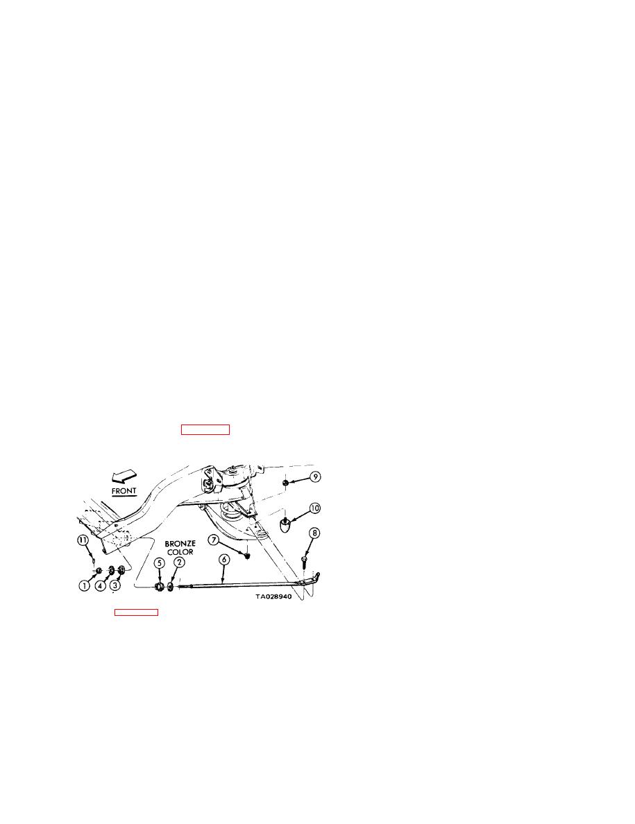
pin (1 1) from the front of the strut (6). Remove (he spring
pin, nut, retainers (2,4), and bushings (3,5).
longitudinal rails and the lower control arms are mounted
on a stationary crossmember. Both control arms have
(3) Remove nuts (7) and rear mounting bolts (8).
replaceable bushings on the inside ends and replaceable
Remove the strut.
ball joints on the outside ends. The upper control arms
b. Installation.
also control the caster and camber adjustments through
eccentric pivot bolts. Tension-type lower ball joints are
(1) Position the retainers and bushings on the strut.
used on all models.
NOTE
a. Replace the lower ball joints if you find more than
0.020 inch up-and-down movement.
The rear retainer is bronze in color.
b. Tighten all front suspension points that contain
(2) Slide the strut into position. Install the mounting
rubber bushings with the full weight of the vehicle on
bolts and tighten to 85 ft-lbs.
its wheels.
(3) Install the bushing, retainer, and nut at the front
c. Never lubricate rubber bushings.
of the strut. Tighten the nut to 50 ft-lbs.
7-2. Lower Control Arm Strut.
(4) Install the spring pin and lower the vehicle.
7-3. Coil Spring.
a. Removal.
(1) Chock the rear wheels and raise the vehicle on
jack stands. Remove the wheel.
(2) Remove the brake caliper and secure it out of the
way. Do not allow the caliper to hang or be supported by
the hydraulic brake hose.
(3) Remove the grease cap, cotter key, locknut,
adjusting nut, washer, and outer bearing.
(4) Slide the rotor from the steering knuckle. Do not
drag the seal or inner bearing over the steering knuckle
thread. The thread, bearing, or oil seal may be damaged.
(5) Remove the mounting screws and the brake
splash shield.
Legend for Figure 7-1:
6. Strut
(6) Disconnect the sway bar from the lower control
7. Nut assembly
1. Nut
arm.
8. Bolt
2. Rear retainer
9. N u t
3. Front bushing
(7) Place a jack under the lower control arm and
10. Jounce Bumper
4. Front retainer
allow l/2-inch clearance between the jack and the arm.
11. Spring pin
5. Rear bushing
(8) Remove the cotter key and back off the nut on
the lower ball joint hub until the top threads arc protected.
Figure 7-1. Lower Control Arm Strut and Related Parts.
7-1


