TM 9-2320-266-34
(3) Install the wormshaft-to-column coupling bolts.
spot") position. Then tighten the locknut securely and
check the torque reading again.
in-lbs, place the wheels in the straight-ahead position and
install the steering arm.
(6) Tighten the steering arm retaining nut to 180
ft-lbs.
7-14. Steering Gear.
a. Removal.
(1) Remove the two wormshaft-to-column coupling
bolts (figure 7-15).
(2) Remove the steering arm from the steering gear.
(3) Remove the steering gear-to-frame bolts and
remove the gear from the vehicle.
b. Installation.
(1) Position the steering gear to the frame and install
the mounting bolts.
(2) Install the steering arm.
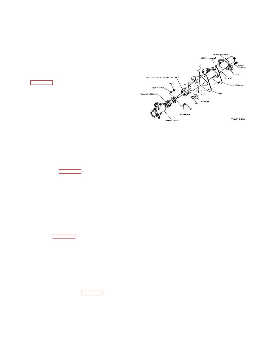
Figure 7-15. Steering Column and Gear Assembly.
Section IV. STEERING COLUMN
b. Installation.
7-15. General Information.
(1) Insert the steering column assembly throuth the
The steering column shaft is connected to the steering
firewall opening.
gear wormshaft with a flexible coupling to absorb road
shock and vibration. A rubber and fabric type coupling is
(2) Position the steering column so the flange face is
used on 4X2 models (figure 7-15). The 4X4 models have
parallel to the fabric coupling face to prevent undue stress
two couplings between the steering column shaft and
on the fabric coupling. Position the column to center the
steering gear: a fabric and rubber coupling at the steering
steering shaft bearing blocks in the pot coupling on the
gear, and a "pot type" coupling at the column shaft.
4X4 models.
7-16. Steering Column.
(3) Connect the steering column coupling flange
with the rubber and fabric type coupling on the steering
a. Removal.
gear wormshaft.
(1) Disconnect the negative (ground) terminal at the
(4) Install the two steering column upper bracket
battery.
bolts. Tighten them finger-tight.
(2) Disconnect the shift linkage from the lower end
(5) With the front wheels in the straight-ahead
of the steering column.
position, center the shaft in the tube.
(6) Position the support plate to the firewall and
flexible coupling (figure 7-15). On 4X4 models, remove
tighten the screws. Slide the "O" ring into position on the
the pot coupling roll pin.
support plate and secure it with the two screws.
(4) Disconnect the electrical wiring connector at the
(7) Tighten the steering column bracket bolts to 110
steering column jacket.
in-lbs. Tighten the steering column coupling-to-steering
(5) Remove the horn pad. Disconnect the horn wire
gear flange nuts to 20 ft-lbs.
and remove the horn switch.
(8) Connect the gearshift indicator pointer to the
(6) Remove the steering wheel retaining nut and
operating bracket on the shift housing in its approximate
washer. Using an appropriate puller, remove the steering
original location. Slowly move the gear selector lever from
wheel.
"1" to "P", pausing briefly at each selector position. The
indicator pointer must aline with each selector position.
(7) Loosen the "O" ring retaining plate screws and
If necessary, loosen the bolt and readjust it to aline the
remove the support plate screws (figure 7-15).
pointer correctly.
(8) Remove the trim panel and the nuts or bolts
(9) Place the steering wheel on the steering shaft
attaching the steering column clamp to the instrument
with the master splines alined. Install the retaining nut and
panel support.
washer, and tighten the nut to 27 ft-lbs. Do not drive the
(9) Lift the column out through the cab.
7-8


