TM 9-2320-266-34
the rotor. Back off the adjusting nut to completely release
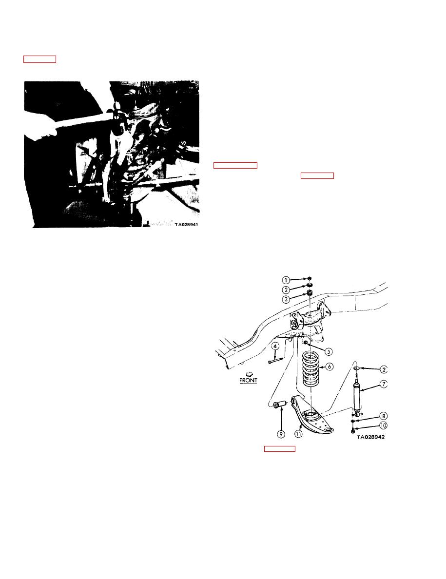
(9) Using a brass drift, strike the ball joint stud until
the bearing preload. Next, tighten the adjusting nut.
the ball joint has separated from the steering knuckle
Install the locknut and cotter key.
(7) Install the grease cap.
(8) Install the caliper on the rotor. Install and
tighten the mounting bolts.
(9) Install and tighten the wheel.
(10) Remove the jack stands and lower the vehicle.
(11) Test operation.
74. Lower Control Arm and Bushing.
a Removal.
(1) Follow the coil spring removal procedure in
(2) Remove the nut (5, figure 7-3) and the hex head
mounting bolt (4) from the crossmember. .
(3) Remove the lower control arm (11).
(4) Press out the bushing (3).
b. Installation.
(1) Press in a new bushing.
Figure 7-2. Removing Lower Ball Joint
(2) Position the lower control arm on the vehicle.
from Steering Knuckle
(3) Install the hex head mounting bolt finger-tight.
(10) Use the jack under the lower control to compress
the coil spring.
(11) Remove the top shock absorber nut.
(12) Remove the lower ball joint stud nut.
(13) Slowly release the jack pressure until the coil
spring pressure is eliminated.
(14) Remove the lower shock absorber retaining nuts.
(15) Remove the shock absorber.
(16) Remove the spring.
b. Installation.
(1) Position the spring on the lower control arm.
Using a jack under the control arm, compress the spring
until the ball joint is properly positioned in the steering
knuckle.
(2) Install the ball joint nut and tighten to 135 ft-lbs.
Install the cotter key.
(3) Install the upper shock absorber bushing and
sleeve. Position the shock absorber, and install the upper
retainer and nut and lower mounting bolts. Tighten the
upper nut to 25 ft-lbs and the lower mounting bolts to
17 ft-lbs (200 in-lbs).
Legend for Figure 7-3:
1. Nut
6.
Coil spring
(4) Connect the sway bar and tighten the link to
7.
Shock absorber
2. Retainer
75 ft-lbs. Remove the jack.
3. Bushing
8.
Washer
4. Bolt
(5) Position the brake splash shield on the steering
9.
Bushing assembly
5. Nut
10.
Capscrew
knuckle and install the mounting screws.
11.
Lower control arm
(6) Slide the rotor assembly onto the spindle,
Figure 7-3. Lower Control Arm and Related Parts.
followed by the outer bearing, washer and nut. Tighten
the adjusting nut to 27 ft-lbs (320 in-lbs) while rotating
7-2


