TM 9-2320-266-34
ring can be snapped into place. If difficulty is encountered,
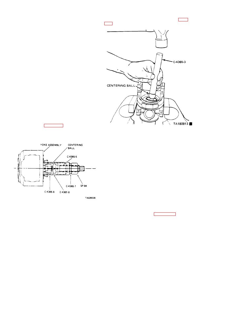
bail on the stud using tool C-4365-3 and a hammer (figure
strike the yoke ear firmly with a hammer to seat the
remaining snapring.
(4) Repeat steps 1 through 3, above, to install the
remairing bearing cups.
6-8. Ball Socket.
a. Removal.
(1) Separate the U-joint between the coupling yoke
and the flange yoke by pressing out the bearing cups (para.
graph 6-7).
(2) Pull the flange Yoke and cross, with the ball socket,
as a unit from the centering half.
b. Inspection.
(1) Clean the ball seat insert bushing, and inspect it
for wear. [f worn, replace the flange yoke and cross
assembly.
(2) Pry the seal from the ball cavity
(3) Remove the washers, spring, and three ball seats
(4) Clean and inspect the centering ball service seats,
spring, and washer. If any of these parts are worn, replace
them.
(5) To remove the centering ball, use the fol-
lowing tools: C4365-5, C-4365-6, C-4365-7, C-4365-8,
and SP-84. Refer to figure 6-12.
Figure 6-13. Centering Ball Installation.
(6) Draw the ball off the ball stud.
(7) Clean and respect the centering ball.
(2) Using the grease provrded in the ball seat kit, lub-
ricate all parts before assembling them into the cavity.
(3) Assemble the ball seat in this order: spring, small
outside diameter washer, three ball seats with the large
opening facing out, large outside diameter washer, and seal.
NOTE
The ball seat kit comes with two springs,
The spring dyed yellow IS to be used for
this installation. [f the springs are not
dyed, then use the shortest spring in the
kit. Discard the remaining spring.
(4) Lubricate the seal lip. Using a 7/8-inch
socket or applicable size tool, press the seal lip in un-
til it is flush with the yoke. The sealing lip should
tip inward.
Figure 6-12. centering Ball Removal.
(5) Fill the cavity with the grease that is provided in
the kit.
c. Installation.
(6) Reassemble the U-Joint (paragraph 6-7).
(1) Install the centering ball on the stud. Seat the
6-6
Change 6


