TM 9-2320-266-34
(3) Disconnect the hydraulic brakeline at the
(1) Position the rear axle assembly, On 4X4
flexible coupling.
models, install the spacers.
(4) Disconnect the parking brake cables.
(2) Install the spring "U" bolts and tighten the
nuts to 180 ft-lbs, Install the shock absorbers. Tighten
(5) Disconnect the rear propeller shaft at the
nuts to 85 ft-lbs.
differential pinion flange and secure it out of the way.
(3) Connect the parking brake cables.
(6) Remove the shock absorbers and the rear
spring "U" bolts.
(4) Connect the hydraulic brakeline at the flexible
coupling. Install the hub and drum assemblies.
(7) Remove the axle assembly from the vehicle.
(8) Remove the axle spacers (4X4 models only).
shaft.
b. Installation.
(6) Check the brake adjustment and bleed the
I
NOTE
brakes.
If axle assembly is changed, record part
(7) Install the rear wheels.
number on DA FORM 2408-10 (Equipment
(8) Lower the truck and check the differential
Component Register).
lubricant level. Test for proper operation.
Section Ill. PROPELLER SHAFTS
6-6. General.
Refer to TM 9-2320-266-20 for instructions on removal
and replacement of the propeller shafts and U-joints (except
constant velocity U-joint).
6-7, Constant Velocity (CV) UJoint (4X4 Models
Only).
a. Disassembly.
(2) Remove the U-joint bearing cup snaprings, if so
equipped.
NOTE
Production model U-joints have plastic
retainers instead of snaprings. To dis-
assemble the joint, you will have to break
the retainer. You will have to replace the
joint since it does not have grooves for a
snapring.
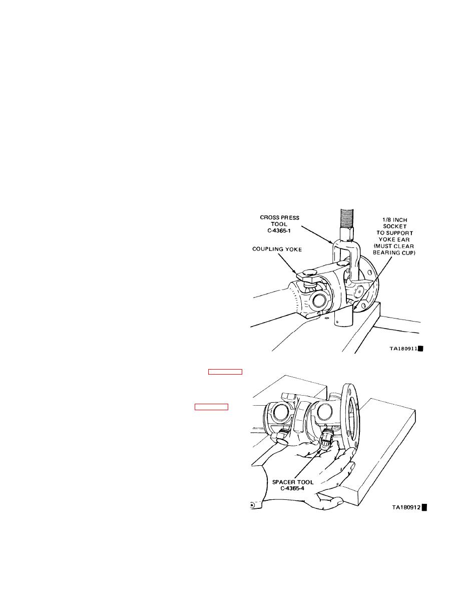
Figure 6-10. Bearing Cup Removal.
(3) Position the U-joint on a workbench or press with
the shaft yoke supported by a 1-1/8-inch socket (figure 6-10)
(4) Using tool C-4365-1, press (or drive) the lower
bearing cup out of the yoke. If the bearing cup will not
come out all the way, lift the cross and insert spacer tool
C4365-4 between the seal and bearing cup (figure 6-11).
Then, continue to press the cup out.
(5) Repeat steps 3 and 4, above, to remove the
remaining bearing cups.
b. Assembly.
(1) Partially install one bearing cup into one side of
the yoke, and turn this yoke to the bottom.
(2) Insert the cross into the yoke so that the bearing
cup seats into it. Install the opposite bearing cup part way.
(3) Press the bearing cups into position while working
the cross up and down to insure that the bearings don't
bind. Continue pressing the cups in until the retaining ring
groove of one of the cups clears the inside of the yoke.
Install the snapnng. Continue to press until the other snap-
Figure 6- 11. Spacer Placement.
6-5
Change 6


