TM 9-2320-266-34
b. Throttle Pressure. Throttle pressures cannot be tested
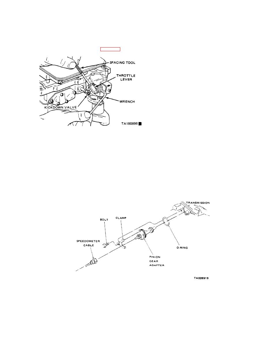
4-16. Speedometer Drive Pinion Gear Assembly
accurately; therefore, the transmission linkage adjustment
(4X2 Models).
should be measured if a malfunction is evident.
Removal and Installation. Refer to figure 4-34.
(1) Insert the gage pin of tool C-3763 between the
a. Remove the bolt and the retainer securing the
throttle lever cam and kickdown valve (figure 4-33),
speedometer pinion adapter in the extension housing.
b. With the cable housing connected, carefully work
the adapter and pinion out of the extension housing.
c. Disconnect the cable from the adapter.
d. Place a new adapter into the transmission.
e. Install a clamp and bolt and torque to 100 in-lbs.
f. Reconnect the cable.
4-17, Replacing the Output Shaft Oil Seal
(4X2 Models Only).
a. Mark the parts for reassembly. Disconnect the pro-
peller shaft at the rear universal joint. Carefully pull the
shaft yoke out of the transmission extension housing.
NOTE
Be careful not to scratch or nick the ground
surface on the sliding spline yoke when re.
Figure 4-33. Throttle Pressure Adjustment,
moving and installing the shaft assembly.
(2) BY pushing in on the tool, compress the kickdown
b. Remove the extension housing boot.
valve against its spring so the throttle valve is completely
c. Remove the extension housing yoke seal with tool
bottomed inside the valve body.
C-3985.
(3) As force is being exerted to the compressed spring,
turn the throttle lever stop screw with an allen wrench until
the head of the screw touches the throttle lever. The throt.
Figure 4-35. Deleted.
tle lever cam should be touching the tool and the throttle
valve should be bottomed. Make the adjustment with the
spring fully compressed and the valve bottomed in the valve
body
Figrue 4.34. Speedometer Drive.
4-23
Change 6


