TM 9-2320-266-34
CHAPTER 5
REPAIR OF THE TRANSFER ASSEMBLY
5-1. General Information.
(1) Place the transfer shift lever in HI.
(2) Loosen both swivel rod clamp lockscrews at the
a. Description. The transfer assembly provides full-time
shifter assembly as shown in figure 5-2. Both rods must be
four-wheel drive, It is a two-speed unit which provides
free to slide in the swivels.
speed reduction and transmits power from the transmission
to the front drive axle and rear drive axle by means of two
conventional propeller shafts. A differential unit within the
transfer case allows front and rear axles to remain in contin-
uous drive while allowing the drive shafts to turn at slightly
different speeds with the control lever in HI or LO. This
permits driving at normal highway speeds. The transfer
case differential is locked out in the HI LOC or LO LOC
position. This causes the front and rear drive shafts to move
at identical speeds, thus providing positive front and rear
wheel drive,
b. HI and LO Ranges. The transfer's two-speed feature
consists of a 1:1 ratio (direct drive) high range and a 2.01:1
ratio speed reduction in low range.
c, Transfer Control. The speed range and lock positions
are controlled by a single shifting lever having five positions:
HI LOC, HI, N, LO, and LO LOC. See TM 9-2320-266-10
for operating instructions.
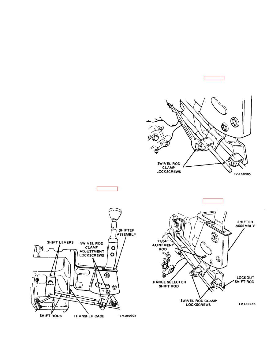
Figure 5-2. Loosening the Lockscrews.
5-2. Service Procedures.
(3) Put the transfer shift lever in the cabin "N" and
insert an 1l/64-inch diameter rod through the alinement
holes in the shifting housing (figure 5-3).
Figure 5-3. Alinement Rod in Position.
Figure 5-1. Shifter Assembly and Linkage.
Change 7
5-1


