TM 9-2320-266-34
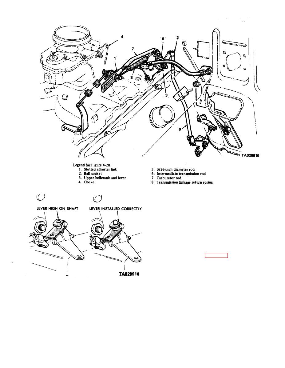
Figure 4-28. Throttle Rod Adjustment.
4-14. Hydraulic Control Pressure Tests.
a. Line Pressure and Front Servo ReleasePressure. Line
pressure and front servo release pressure tests must be made
in the "D" position with the rear wheels free to turn. The
transmission fluid must be at normal operating temperature.
vehicle.
(2) Connect two 100 psi pressure gages (minimum) to
the pressure take-off points at the side of the accumulator
and at the front servo release (figure 4-30).
(3) With the control in "D speed up the engine
slightly until the transmission shifts into direct drive. (The
front servo release will then be pressurized.) Reduce engine
Figure 4-29. Reposition Throttle Lever on Shaft.
speed slowly to 1,000 rpm. Line pressure must be 54-60 psi,
g. Assemble the slotted adjustment (1) to the carburetor
and front servo release pressure must not be more than 3 psi
lever pin and install the washer and retainer clip. Assemble
below the line pressure.
the transmission linkage return spring (8) in place.
(4) Disconnect the throttle linkage from the trans-
h. Check freedom of operation by moving the slotted link
mission throttle lever and move the throttle lever gradually
at the carburetor to the full rearward position. Allow it to
to the full throttle position. The line pressure must rise to a
return slowly, making sure it returns to the full forward
maximum of 90-96 psi just before or at kickdown into low
position.
gear. Front servo release pressure must follow the line pres-
sure up to the kickdown point and should not be more than
i. Connect the choke rod (4), or remove the blocking
future.
3 psi below line pressure.
4-21


