TM 9-2320-266-34
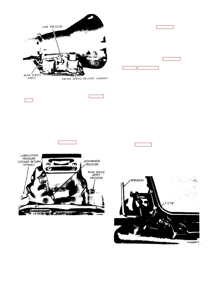
c. Rear Servo "Apply" Pressure.
take-oft' point at the rear servo (figure 4-31).
(2) With the transmission control in the "R" position
and the engine speed set at 1,600 rpm, the reverse servo
"apply" pressure should be 230 to 260 psi.
d. Governor Pressure.
pressure take-off point, located at the lower left side of the
extension near the mounting flange (figure 4-31).
(2) Governor pressures should fall within the limits
given in table 4-2 (paragraph 4-3). If they are incorrect at
the given speeds, the governor valve and/or weights are prob-
ably sticking.
e. Throttle Pressure. There is no throttle pressure test.
Incorrect throttle pressure should only be suspected if part-
throttle upshift speeds are either delayed or occur too early
Figure 4-30. Pressure Test Locations (Right Side of Case).
in relation to vehicle speeds. Engine runaway on either up.
shifts or downshifts can also indicate incorrect (low) throttle
graph 4-15, below. If front servo release pressures are less
pressure setting. Never adjust the throttle pressure until the
than pressures specified and line pressures are within limits,
transmission throttle linkage adjustment has been verified to
there is excessive leakage in the front clutch and/or front
be correct.
servo circuits. Always inspect the external transmission
4-15. Hydraulic Control Pressure Adjustments.
throttle lever for looseness on the valve body shaft when
making the pressure tests.
a. Line Pressure.
incorrect throttle pressure setting
An
will cause incorrect line pressure readings even though the
b. Fluid Pressure. Test fluid pressure at the same time
line pressure adjustment is correct. Always inspect and
that you test line pressure and front servo release pressure.
correct the throttle pressure adjustment before adjusting
(1) Install a "T" fitting between the cooler return line
the line pressure. The approximate adjustment is 1-5/16
fitting and the fitting hole in the transmission case at the rear
inches, measured from the valve body to the inner edge of
left side of the transmission (figure 4-31). Connect a 100
the adjusting nut (figure 4-32). However, due to manufac-
psi pressure gage to the "T" fitting.
turing tolerances, the adjustment can be varied to obtain the
specified line pressure. The adjusting screw may be turned
with an allen wrench. One complete turn of the adjusting
screw changes the closed throttle line pressure approximately
1-2/3 psi. Turning the adjusting screw counterclockwise in-
creases the pressure, and clockwise decreases pressure.
Figure 4-31. Pressure Test Locations (Rear End of Case).
(2) The fluid pressure should be 5-15 psi at 1,000
engine rpm, with the throttle closed and the transmission in
direct drive. It will be approximately double when the throt-
tle is opened to maximum line pressure.
Figure 4-32. Line Pressure Adjustment.
4-22


