TM 9-2320-289-34
4-3.
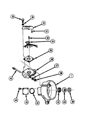
ALTERNATOR TESTING AND REPAIR (M1010) (Con’t).
10.
11,
NOTE
If 1 rectifier was determined to be good in step 8, but other rectifier had to
be replaced, terminal loops at each lead (22) will have to be cut to
separate positive rectifier (28) from negative rectifier (20). Ensure that
leads are tagged for assembly if this is done,
Remove positive rectifier (28) and negative rectifier (20) from slipring end housing (1).
Remove 2 upper housing bushings (18), output terminal bushings (19), and lower housing
bushings (27) from slipring end housing,
Tag connector (34) leads and
disconnect from AC “terminal studs
(45) and regulator holder (44).
CAUTION
DO NOT pry on regulator (31) to
remove.
Failure to follow this
caution may result in damage to
regulator.
12.
Remove 4 screws (29), Iockwashers
(30), and regulator (31 ). Remove
and discard gasket (35). Discard
Iockwashers.
CAUTION
Before
changing
p o s i t i o n of
adjustment screw (32), ensure
that “HI” position hole in regulator
(31)
is
clear of obstructions.
Failure to follow this caution may
result in damage to regulator.
13.
14.
15.
16.
Ensure that adjustment screw (32) is
in “HI” position if regulator (31) will
not be replaced.
Remove 3 nuts (38), washers (37),
and AC terminal studs (45).
NOTE
Perform step 15 only if brush holder adapter was removed.
Pull connector (34) lead through access hole and grommet in slipring end housing (1).
Remove regulator holder (36). Remove 2 screws (33) and connector.
Remove 4 screws (44), cover plate (43), and “ O“ ring (42) from slipring end housing (1).
Remove inner seal (39). Insert punch in pilot hole on cover plate side of slipring end housing.
Drive out slipring bearing (40) and outer seal (41). Discard seals and “O“ ring.
TA50788
4-17