TM 9-2320-289-34
4-2.
ALTERNATOR TESTING AND REPAIR (ALL EXCEPT M1010) (Con’t).
130
14,
15,
16,
17,
18.
19.
20.
21.
22.
Install new battery positive (+) terminal (26) from outside. On inside, install new fiber insulator
(25), new bus bar (15), new nut (14), and nut (17).
Position voltage regulator (12). Retract brushes into brush holder assembly (9) and retain
retracted brushes with a suitable retainer. Ensure that retainer extends through end frame (1)
when brush holder assembly is installed.
Install brush holder assembly (9) over voltage regulator (1 2).
Install diode trio (20) and resistor (13). Position rectifier bridge-to-regulator jumper wire (10) at
top screw (11) hole. Install 3 screws (11).
Position plastic insulator (29) in hole in outside of end frame (1).
Install new “R” terminal stud (28) from outside. On inside, install new fiber insulator (30) on
stud .
Install new “R“ terminal bar (19) and secure with new nut (16).
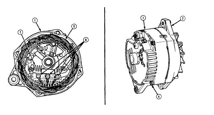
Install stator (5) to end frame (1) alining 3 stator leads with rectifier bridge (7) terminals. Install
3 nuts (6) securely with brushes retracted.
Aline dowel pin with dowel pin hole and install drive end frame (2) onto end frame (1), Install 4
bolts (4) ,
Turn pulley and fan to ensure that they spin freely and without noise. Remove retainer which
was used ‘to secure brushes in their retracted position.
TA50785
4-13