TM 9-2320-266-34
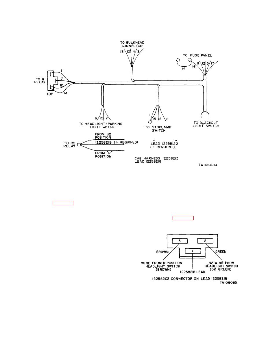
Figure 25-2. Blackout Lighting Kit Cab Harness.
(11) If vehicle does not have the relay, as is the
switch area, and then route remaining wires to the left side
case with the ambulance, install additional relay 12258170.
of vehicle through instrument panel following route of pro-
duction harness (figure 25-2).
This relay will be designated R2 and must be mounted in
(7) Remove headlight switch by first depressing the
the same manner as first relay, directly to the left of the
knob and stem release button on the bottom of the switch
first relay. In the kit, find lead, 12258218, with connector
housing.
12258202 attached (figure 25-3).
(8) Pull knob to release and remove the knob and
(12) Attach connector 12258202 to the R2 relay.
stem. Remove spanner nut, and pull switch out far enough
to separate connector.
(9) Position relay 12258170 on bottom lip of
dashboard so that first hole is approximately 1-5/8 inches
to the right of the T-handle brake release and, using relay
as a template, mark dashboard.
(10) Drill holes 3/16" diameter at both hole loca-
tions and secure relay with two MS35206-245 screws, two
MS3533S-31 lockwashers and two MS35649-282 nuts.
Attach three-terminal connector 12258202, which retains
wires 7, 11, 12, and 13, to relay which is designated as R 1
relay.
NOTE
At this point it is necessary to deter-
Figure 25-3. Connector on Lead 12258218.
mine if the vehicle has a parking light
relay which is located directly to the
right of the fuse box.
Change 6
25-2


