TM 9-2320-266-34
(36) Remove green/black wire from receptacle 14,
cut off the terminrd, and tape wire end securely- (accessible
from underside of dashboard).
(37) Insert terminal end of harness wire 13 into re-
ceptacle 14.
(38) Insert harness wire 4 into receptacle 31, wire 10
into receptacle 27, and wire 3 into receptacle 28.
(39) Tie slack wires together with MS3367-1 -9
cable strap.
(40) Electrically disconnect voltage indicator, if
vehicle is so equipped.
(41) Remove instrument panel from dashboard and
at extreme right side of the instrument panel using template
12258220, provide one oval hole and four l/4-inch
diameter holes.
(42) Mount blackout light switch in the oval hole,
so its three control levers can be easily operated by the
vehicle operator, and secure with four MS35191-274
screws.
NOTE
Lamp removal may be accomplished by
reaching behind instruments, locating
lamps with the fingers, twisting slightly
and removing.
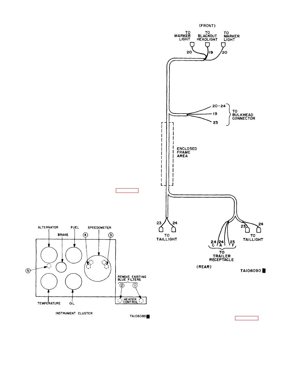
(43) Remove three 158 instrument lamps (located
behind instruments) and two 1892 lamps in heater control
area. Install the five red rubber filters, 12258219, over the
three 158 instrument lamps and the two 1892 lamps in
the heater control area and reinstall lamps (figure 25-7).
(44) Connect cab wiring harness to blackout light-
ing switch by attaching harness connector to switch.
(45) Reconnect voltage indicator (if necessary),
and reinstall instrument panel and glove compartment.
This completes cab installation.
Figure 25-8. Main Wiring Harness.
b. Main Harness.
(1) Route rearward portion of main harness
12258214 downward to the left side of steering column
under the hood, retaining forward (shorter) end of harness
in close proximity to bulkhead connector (figure 25-8).
Figure 25-7. Instrument Cluster Lamp Filter Locations.
Change 6
25-5


