TM 9-2320-266-34
(4) Disconnect bracket by removing screw. Dis-
24-23. Personnel Heater Control Box.
connect cable assembly from bracket by removing screw.
a. Removal.
(5) Disconnect shell from cable by removing
(1) Remove 24 volt battery system ground cable.
washer and sliding shell from cable. Remove cable from
grommet.
(2) For the M880 or M882 vehicle, gain access to
control box by removing three screws and one nut retaining
c. Inspection and Repair.
guard. Remove guard. For the M886 ambulance, access is
(1) Repair defective wiring.
gained in same way as for heater/ventilator (refer to TM 9-
(2) Reform distorted parts (refer to TM 10-450).
2320-266-20).
(3) Weld cracks (refer to TM 9-237).
(3) Disconnect electrical connector and harness plug
from heater control box assembly.
(4) Replace defective parts.
(4) If repair or maintenance is to be performed only
d. Assembly.
on electrical components, remove two screws and remove
(1) Insert grommet on cable, and insert cable and
unit by sliding panel out of case.
grommet in panel. Slide shell on cable and install washer.
(5) If control box assembly requires replacement,
(2) Connect cable assembly to bracket and secure
remove two nuts along with washers securing control box
with screw. Connect bracket to panel and secure with
assembly to base plate.
screws.
b. Disassembly.
(3) Connect circuit breaker and spacer to panel, and
NOTE
secure with screw and nut.
(4) Position lamp through panel and secure with nut
Before removing electrical wiring, tag
and washer. Install lens.
wire and component with location.
(5) Position switches through panels and secure with
(1) Remove electrical wires from switches. Dis-
nuts, washers, and keyed washers.
connect switches from panels by removing nuts, washers,
(6) Install electrical wiring in accordance with tag
and keyed washers.
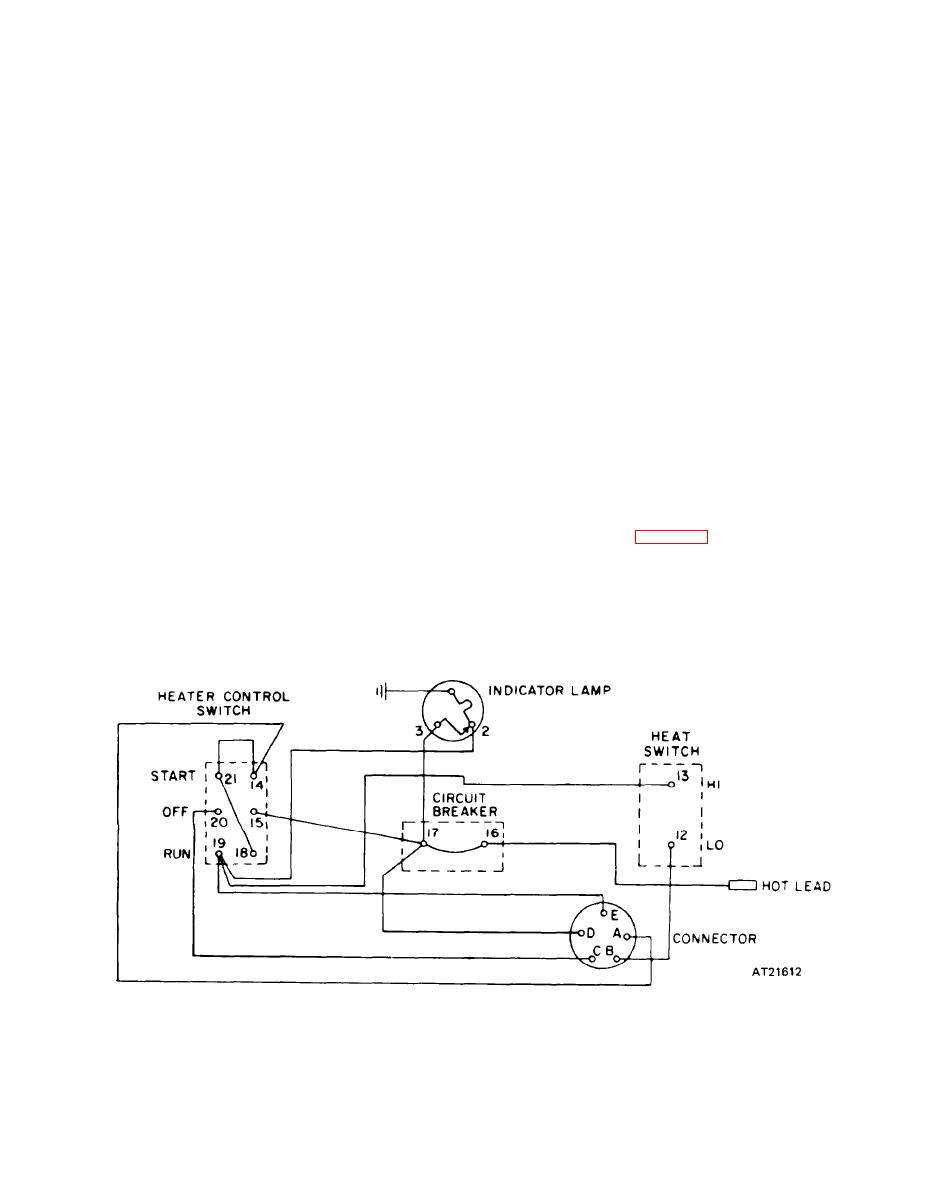
designations or refer to figure 24-7.
(2) Remove electrical wires from lamp. Discon-
e. Installation.
nect lamp from panels by removing lens, nut, and washer.
(1) If repair or maintenance was performed only on
(3) Remove electrical wiring from circuit breaker.
control box electrical components (para. a(4) above), po-
Disconnect circuit breaker. Disconnect circuit breaker
sition assembled electrical components in case and secure
and spacer from panel by removing screw and nut.
with two screws. Proceed to step (5) below.
Figure 24-7. Control Box Wiring Diagram.
Change 5
24-15


