TM 9-2320-246-34
(d) The flame detector switch must transfer with-
in 150 seconds from the moment the heater control switch
was turned on.
NOTE
Ignition may be inaudible. If so, transfer
time of flame detector switch will be used
as the limiting factor for test.
(e) Immediately after the flame detector switch
transfers, turn the HI-LO switch to HI and note current
draw. Draw must not exceed 6.3 amperes.
NOTE
Add 3.5 amperes to maximum current
draw if test is conducted at a temper-
ature that will maintain the fuel valve
thermostat in a closed position.
(9) Observe high heat fuel flow on the flowmeter.
Flow must be more than 0.027 lb/rein., but less than 0.033
lb/rein.
(10) If fuel rates for high heat are not within limits,
turn adjusting screw of the fuel control valve clockwise to
increase fuel flow, or counterclockwise to decrease flow
and retest. If, after adjusting fuel flow for high heat, it is
found that low heat flow is not within limits, it is an indi-
cation that one of the metering holes in the orifice plate is
clogged. Replace fuel control valve assembly.
(11) While heater is burning on high heat, block off
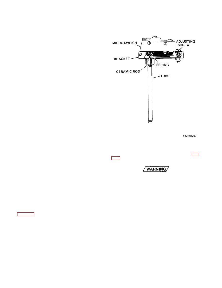
Figure 24-6. Flame Detector Switch.
all flow of ventilating air by covering the heater outlet with
cardboard or sheet metal. The overheat switch must open
and shut off fuel flow in more than 15 seconds, but less
than 30 seconds from the moment air flow was shut off.
24-3). Replaced adapter is retained to heater with three
Replace the overheat switch if not within limits and retest.
screws.
(12) After heater has been burning on high heat for
at least 1 minute, turn heater control switch off. Fuel
flow must drop to zero for more than 1 minute, but less
To prevent escape of poisonous exhaust
than 3-1/2 minutes, and must then automatically stop. Re-
gases, be certain to install exhaust tube
set, or replace, the flame detector switch if not within lim-
retaining clamps securely when perform-
its and retest.
ing the following steps.
(13) To time the blower, mark the combustion air
blower fan with chalk. Start the heater and time the fan
(3) Position heater on base plate. For the M880 or
with a suitable tachometer. Blower speed must be within
M882 vehicle, secure heater to exhaust tube by tightening
the limits of 6,800 to 7,800 rpm with restriction on the
clamp. For the M886 ambulance, secure heater to flexible
heater outlet and an applied voltage of 24 volts.
exhaust tube and secure with clamp.
(4) Secure heater to base plate with two adjustable
h. Adjusting Flame Detector Switch. Refer to
hose clamps. For the M880 or M882, secure hose duct to
adapter with clamp.
(z) Back off on the adjusting screw until the micro-
(5) Connect power cable connector to heater.
switch clicks (or one full turn).
(6) Install adapter and connect fuel line to heater.
(2) Turn adjusting screw slowly in until the switch
clicks, then turn exactly 3/4 turn past the click point.
(7) Install heater guard.
(3) Cement adjusting screw in place with Glyptal
(8) For the M880 or M882, install guard. For the
varnish or suitable substitute.
M886 ambulance, install adapter and cover plate.
i. Installation.
(9) Connect battery ground cable,
(1) Position adapter on heater hot air outlet and
(10) Turn on shutoff cock.
secure with four screws and washers.
24-14
Change 5


