TM 9-2320-266-34
5.
Spacer
Legend
10. Washer
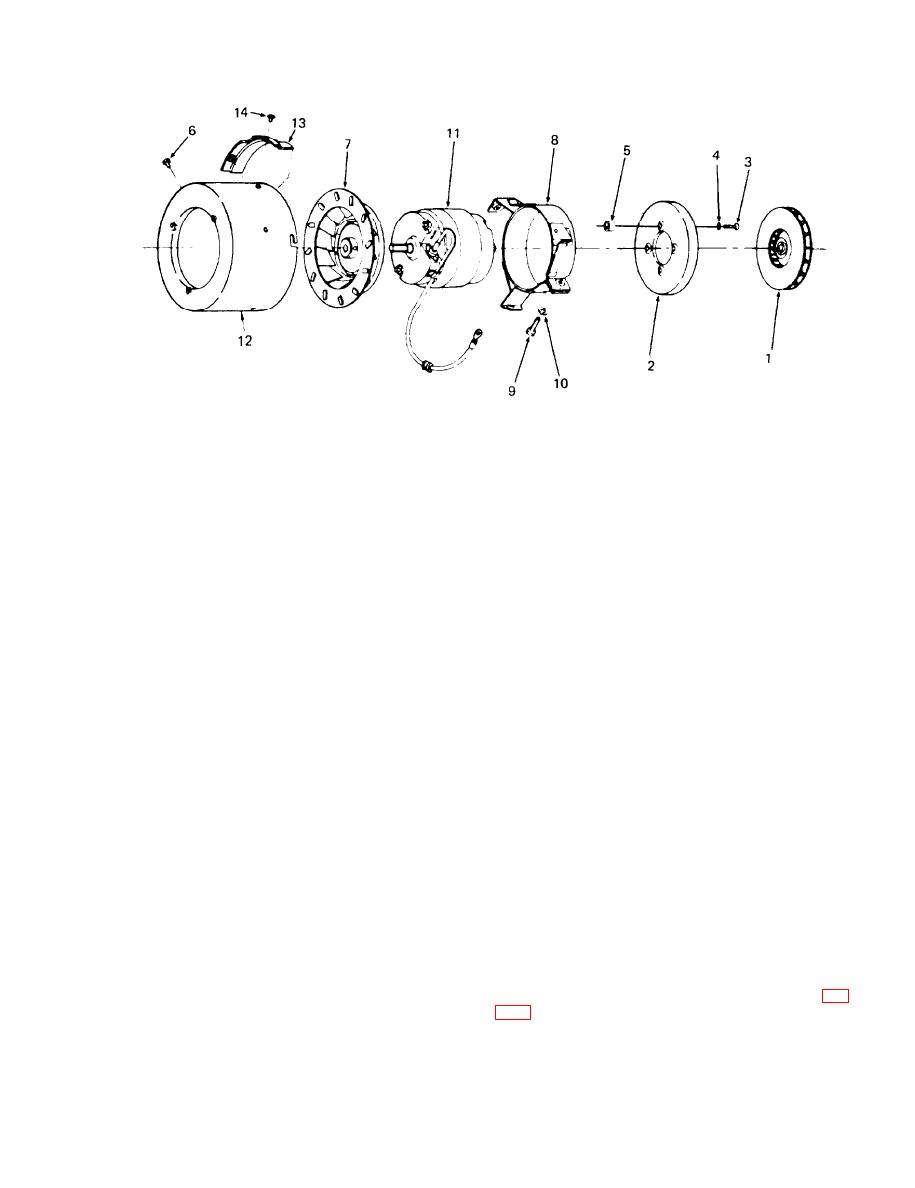
11. Motor (24 vdc)
Screw
1. Wheel assembly, combustion blower
6.
7.
Wheel assembly, blower
12. Housing assembly
2. Header, secondary blower
Bracket assembly, motor mounting
8.
13. Baffle, vent air
3. Screw
9.
Screw
14. Screw
AT33440
4. Washer, lock
Figure 24-4. Ventilating Blower Assembly Component Parts.
d. Inspection and Repair.
(a) Remove housing (12) from bracket (8) by re-
moving screws (6).
(1) Check wiring for condition of insulation and
tightness of electrical connectors.
(1) by loosening setscrew in hub.
(2) Check electrical wires and terminal connections
for continuity, using an ohmeter.
(c) Remove blower header (2) from motor (11)
by removing screws (3), washers (4), and spacers (5).
(3) Inspect heat exchanger for damage or leaks.
(d) Remove blower wheel assembly (7) from
(4) Inspect scoop on burner assembly for distortion.
blower motor (11) by loosening setscrew in hub.
(5) Inspect overheat switch assembly for damage.
c. Cleaning.
(6) Replace all defective parts.
(1) Clean heat exchanger as follows:
e. Assembly.
(a) Scrape as much carbon as possible out of heat
(1) Blower assembly.
exchanger.
(a) Install blower wheel assembly (7, fig. 24-4) on
(b) Clean heat exchanger by soaking in a suitable
blower motor (11) and tighten setscrew. Position motor
solvent. Rinse to remove all traces of solvent and dry
through mounting bracket (8).
thoroughly.
(b) Install blower header (2) to motor (11) with
(2) Clean burner assembly by scraping out all soot
spacers (5), washers (4), and screws (3).
and carbon from inside the casting and burner surfaces.
(c) Install blower wheel assembly (7) by tighten-
(3) Clean air valve assembly by removing all carbon
ing setscrew in hub.
and grease outside of valve.
(d) Install housing (12) to bracket (8) with screws
(4) Clean overheat switch contacts by sliding a clean
(6).
strip of bond paper between points.
---- _ -- --
(2) Assembly of burner.
-------O--
CAUTI N
Do not use an abrasive on switch contacts.
Do not attempt to bend the blade or con-
assembly (23).
tact arm or change the setting of the
adjusting screws.
24-11
Change 5


