TM 9-2320-266-34
(4) Use a feeler gage to select the proper thickness of
shims that will fit snugly between adapters SP-561 and
SP-3250 (figure 20-16).
NOTE
This measurement will determine the cor-
rect thickness shim pack for installation
behind the rear pinion bearing cup and the
carrier casting.
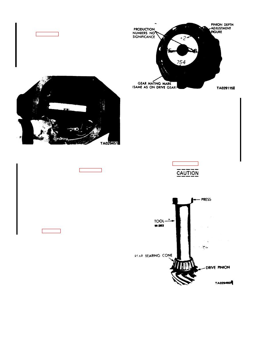
Figure 20-17. Drive Pinion Markings.
(6) If the marking is negative, add the correct amount
of shims. If the marking is positive, subtract the correct
amount of shims. Shims are available in 0.003, 0.005, and
0.010 inch thicknesses.
(7) Remove the tool and adapters from the axle
housing.
(8) Remove the rear pinion bearing cup and install
the correct shim pack.
(9) Reinstall the rear bearing cup as described in a,
above.
Figure 20-16. Determining Shim Pack Thickness for Drive
Pinion Depth of Mesh.
(10) Lubricate the cone, and install it on the pinion
shaft using tool W-262 (figure 20-17.1 ).
(5) To select a shim pack, read the markings on the
end of the pinion head as shown in figure 20-17. One num-
ber is found on both the drive pinion and the ring, which
indicates a matched gear set. Directly opposite this number
To prevent damage to the bearing, do not
will be one with a "+" or "-" before it, or the number will
strike the bearing cage during installation.
be "0." This number must be positively identified before
continuing the assembly procedure. Midway between the
two sets of numbers described above are numbers and letters
which are etched for manufacturing purposes only. But as
one of these numbers may be "0," it might be confused
with the number needed for the assembly procedure. A
rule to follow would be to first examine the shaft end for a
positive or negative number. If a positive or negative num-
ber is not etched on the pinion head, then the number will
be zero (see table 19-1).
Figure 20-17.1. Installing the Front Pinion Bearing Cone.
20-6
Change 1


