TM 9-2320-266-34
CHAPTER 20
REPAIR OF THE FRONT DIFFERENTIAL ASSEMBLY
20-1. Differential Case and Drive Pinion.
with a feeler gage. A 0.003-inch feeler gage should not be
able to enter between the bearing cap and cup. If it does,
A close examination of the axle assembly can often reveal
the bearing cup may have turned in the carrier, causing ex-
valuable information as to the extent and type of repairs or
cessive wear.
adjustments necessary. Since the most frequent causes of
axle noise are improper backlash, differential bearing preload,
(5) Turn the gear carrier and tube assembly in the
or both, a few simple adjustments may be all that is necessary
holding fixture so that the drive pinion shaft is vertical.
to correct the deficiency. Therefore, before disassembling
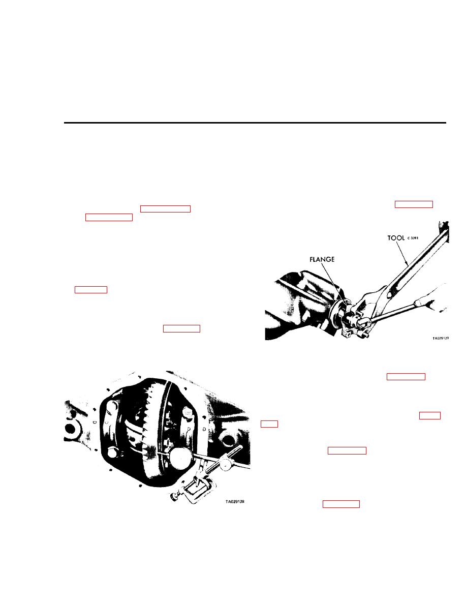
(6) Remove the nut from the drive pinion shaft, hold-
the differential assembly, make the following checks: drive
ing the companion flange with tool C-3281 (figure 20-2).
gear and pinion backlash (paragraph 20-3), pinion bearing
preload (paragraph 20-2), and tooth contact pattern (para-
graph 204). Record and analyze the results. These meas-
urements will aid you in making the necessary repairs to the
axle assembly.
a. Removal and Disassembly. If after the above tests and
adjustments the deficiency is not corrected, then proceed as
follows:
(1) Remove the front axle assembly from the truck
(see chapter 6). Place the carrier and tube assembly on a
holding fixture with the carrier cover opening facing upward.
and other internal parts with a suitable solvent.
back face of the drive gear for runout. A reading in excess of
0.006 inch might indicate a loose drive gear or a sprung dif-
Figure 20-2. Removing or Installing Companion
ferential case.
Flange Nut.
(8) Remove the drive pinion seal assembly.
(9) Turn the gear carrier and tube assembly in the
holding fixture. Remove the differential bearing cups. Note
the matching marks on the carrier and bearing caps (figure
(10) Install carrier spreader tool W-129-A, with the
dowels completely engaged, to full depth in the holes pro-
vided in the housing (figure 20-5). Be sure two hold-down
clamps are properly and firmly holding the spreader in
position.
(11) Install a long stud in the carrier cover bolt hole
on the left side of the housing. Install a dial indicator and
fixture, and position the indicator pointer on the opposite
side of the housing (figure 20-5).
(12) Spread the carrier until a 0.015 to 0.020 inch
Figure 20-1. Checking Drive Gear Runout.
spread is shown on the indicator. Do not exceed this limit or
(4) Check the clearance between the differential bear-
it will result in permanent distortion of the housing.
ing cap and the bearing cup by prying against the drive gear
20-1


