TM 9-2320-266-34
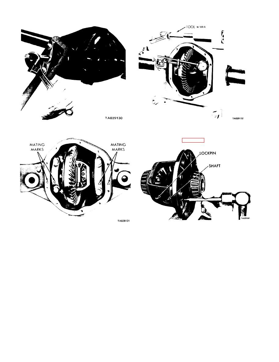
Figure 20-3. Removing Companion Flange (Typical)
Figure 20-5. Differential Carrier Spreader and Indicator.
(19) Drive out the lockpin securing the differential
pinion shaft to the case (figure 20-6).
Figure 20-6. Removing Differential Pinion Shaft Lockpin.
Figure 20-4. Marks on Bearing Caps and Carrier.
(20) Remove the differential pinion mate shaft, the
(13) Remove the dial indicator fixture.
differential pinion mates, and the thrust washers (one in
(14) Pry the differential case assembly loose with a
back of each gear). If you found excessive drive gear
large screwdriver or bar and lift it from the carrier. Pry out
run out, determine the cause.
the differential case assembly as straight up as possible, using
(21) If you found no uneven surfaces or other causes
leverage against the differential case and carrier to prevent
preventing good drive gear alinement, check the runout of
damage. Place the differential case assembly in a holding fix-
the drive gear mounting flange surface.
ture or in a vise with soft jaws.
(22) Install the differential assembly (with drive gear
(15) Remove the gear carrier spreader.
removed) in the carrier housing. Attach a dial indicator and
(16) Knock out the inner oil seals from the axle tubes
check the runout of the drive gear mounting face of the dif-
with an old axle shaft or rod.
ferential case flange.
(17) Remove the cups from the differential case bear-
(23) If the total indicator reading taken while rotating
ings. If the bearing cones and cups are not worn or damaged
the differential case indicates excessive runout, replace the
and are to be reassembled, make certain each mating cup
differential bearing cones or correct the condition by machin-
and cone are paired together with the bearing cap.
ing a light cut from the drive gear mounting surfaces on the
case flange.
(18) Remove the drive gear mounting bolts and remove
the gear. Discard the bolts.
20-2


