TM 9-2320-266-34
the parts for defects. Check the ball guide ends for damage.
bushing wear is excessive, replace the entire side cover and
Replace defective parts.
bushing assembly.
(4) Hold the ball nut with the helical grooved bore in
a horizontal position with the ball guide holes facing upward.
Position the shallow side of the rack teeth toward the left as
viewed from the steering wheel end. Insert the wormshaft,
alining the wormshaft grooves with the grooves in the nut.
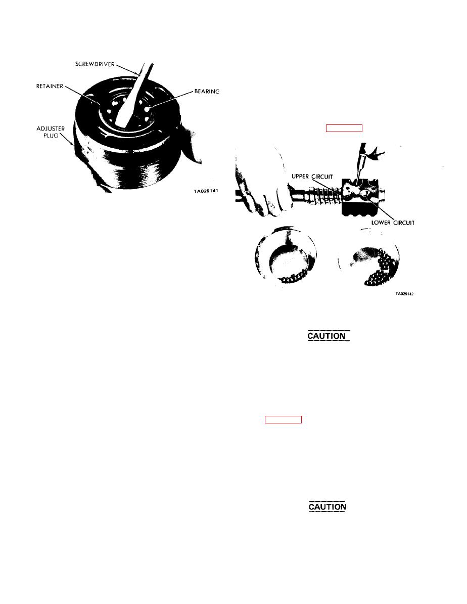
(5) Count 27 balls (the number of balls for one
circuit) into a clean container. Place 20 of these balls into
one of the guide holes. It may be necessary to push them
in with the aid of a pin punch (figure 21-4).
Figure 21-3. Removing Lower Bearing Retainer.
b. Sector Shaft Bushing Replacement - Housing.
(1) Support the steering gear housing in an arbor
press. Press the sector shaft bushing and seal from the
housing.
is necessary after installation as service bushings are machined
to size. Install the seal using a suitable tool. Install a new
seal whenever a seal has been removed, or if signs of wear
are evident.
c. Wormshaft Bearing - Adjuster Cup Replacement.
(1) Hold the wormshaft adjuster in a vise. Using a
Figure 21-4. Filling Ball Circuit (Closed Type).
slide hammer, remove the bearing cup.
(2) Press the new bearing cup into position using
adapter C-4176.
Do not rotate the wormshaft until both
d. Wormshaft Bearing Cup Replacement - Housing.
circuits, complete with balls, are installed.
(1) Drive the bearing cup out of the housing with the
(6) Place one set of ball guides on the bench, with the
aid of a drift or punch.
ball groove in each guide half facing upward. Position the
(2) Press the new bearing cup into position using
remaining seven balls into the groove of one ball guide half
adapter C-4176.
and cover them with the second guide half. Holding the two
halves together, plug the opening on each end with a dab of
21-3. Ball Nut.
grease to keep the balls in place while installing the guide
a. Side-Loading Guides. If there is no indication of
assembly (figure 21-5).
binding or tightness in the ball bearing nut assembly when
(7) Push the guide assembly into the guide holes of
the wormshaft is rotated, disassembling the unit is unneces-
the nut. If a slight bind is encountered, tap it lightly into
sary. If, however, tightness or binding is noticed, disassemble,
place with a screwdriver handle. After the guide assembly
clean, and inspect the unit to determine the cause. Use the
is in position, one ball circuit is completed.
following procedure:
(8) Use the same procedure to assemble the second
(1) Remove the screws and ball retaining clamp.
ball circuit. Install the ball guide clamp and tighten the
Remove the guides from the nut.
screws to 30 ft-lbs. Rotate the nut on the worm to check
(2) Invert the nut, rotate the wormshaft in both
for binding and free movement.
directions to permit the balls to drop out. (Make sure your
work area is clean.) Having removed all of the balls, remove
the nut from the wormshaft.
Do not rotate the nut to the end of the
(3) Wash the parts, using a cleaning solvent, and dry
worm threads or damage will result to the
them with compressed air. Using a magnifying glass, inspect
ball guides.
21-2


