TM 9-2320-266-34
(4) Insert the installing screw and plate assembly,
facing upward, through the seal opening working inside of
the chain case cover.
(5) Place the seal in the cover opening, with the seal
lips down. Place the seal installing plate in the new seal,
with the protective recess toward the lip of the seal retainer
(tool SP5598, part of tool C-3506).
(6) Install a flat washer and nut on the installing
screw, hold the screw, and tighten the nut.
(7) The seal is properly installed when the seal case is
tight against the face of the cover.
e. Ins tailing the Cover.
(1) Be sure the mating surfaces are clean and free from
burrs.
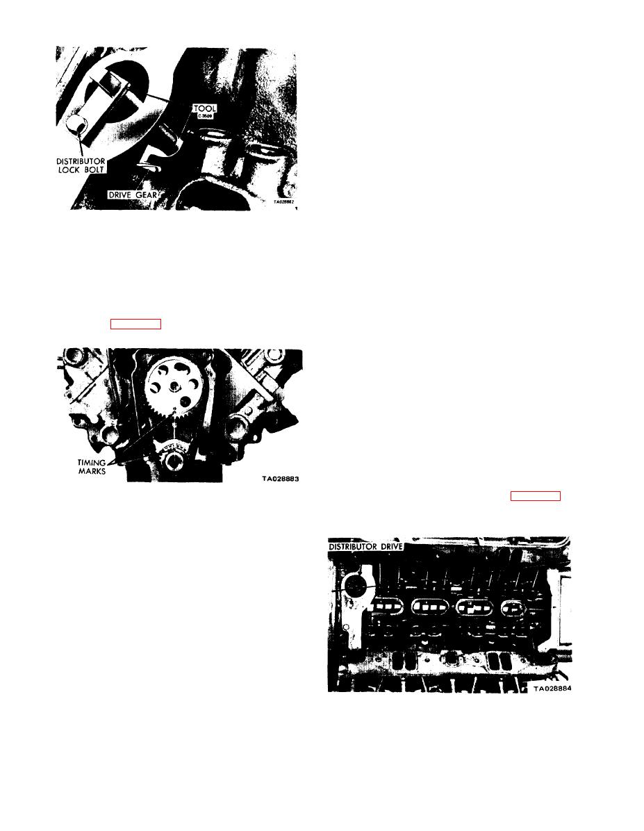
Figure 3-9. Camshaft Holding Tool C-3509.
(2) Using a new gasket, install the chain case cover to
avoid damaging the oil pan gasket. First, tighten the chain
(7) Turn the crankshaft and camshaft to lineup with
case cover capscrews to 30 ft-lbs. Then tighten the oil pan
the keyway locations in their respective sprockets.
capscrews to 17 ft-lbs.
(8) Lift the sprockets and chain (keep the sprockets
(3) Lubricate the seal lip. Position the vibration
tight against the chain in the position described).
damper hub slot on the key in the crankshaft, and slide it on
(9) Slide both sprockets simultaneously over their
the crankshaft.
respective shafts. Use a straightedge to check alinement of
timing marks (figure 3-10).
(4) Tap the vibration damper on the crankshaft. Then
install the retainer bolt with a washer and tighten it to 135
ft-lbs.
(5) Position the pulley on the vibration damper and
attach it with bolts and lockwashers. Tighten to 17 ft-lbs.
(6) Install the fuel pump and fuel lines.
(7) Install the water pump and housing assembly,
using new gaskets. Tighten bolts to 30 ft-lbs.
(8} Install the radiator, fan and belt, and hoses. Close
the drains.
(9) Fill the cooling system.
(10) With the timing indicator on "O;' install the dis-
tributor drive gear with the slot pointing to the first intake
manifold bolt on the left side of the engine (figure 3-11).
Figure 3-10. Alinement of Timing Marks.
(11) Reconnect the battery ground cable,
(10) Install the fuel pump eccentric, cup washer, and
camshaft bolt. Tighten the bolt to 35 ft-lbs.
(11) Measure the camshaft end play. If it is over
0.010 inch, install a new thrust plate.
(12) Replace the timing chain cover oil seal (d, below).
(13) Replace the timing chain cover (e, below).
d. Replacing the Oil Seal (Cover Removed).
(1) Using a drift and hammer, tap lightly at several
places around the seal case to deform the oil seal case
inward.
(2) Engage the seal case with vise grips. Twist and
pull on the vise grips at several places around the seal case to
remove it.
(3) Insert the installing screw through the installing
plate (part of tool C-3506).
Figure 3- 11. Position of Distributor Drive Gear,
3-6


