TM 9-2320-266-34
(4) Carefully position the cylinder heads on the engine
block.
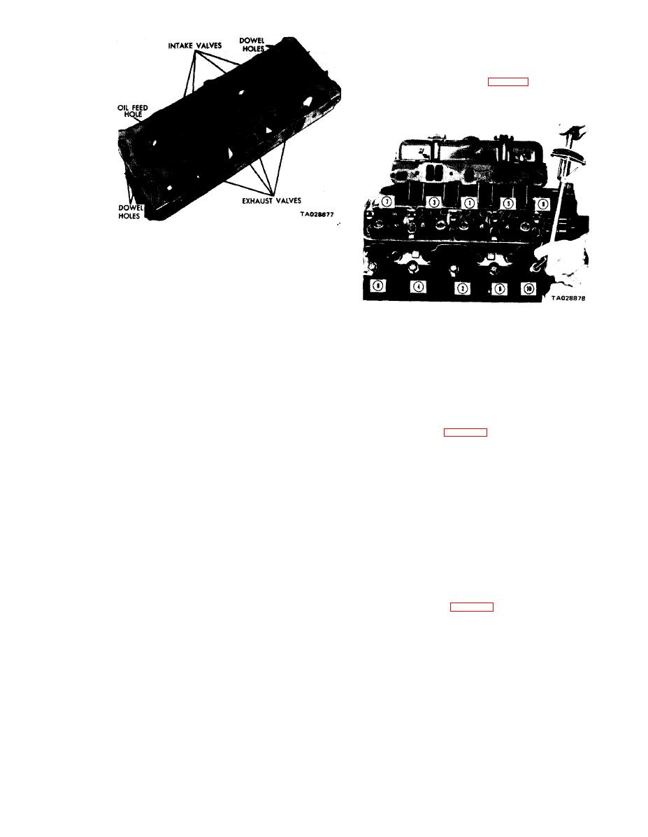
(5) Install the cylinder head bolts, Tighten them to
50 ft-lbs in the sequence shown in figure 3-5. Then, repeat-
ing the sequence, tighten the head bolts to 95 ft-lbs.
Figure 3-4. Cylinder Head Assembly.
a. Removal.
(1) Disconnect the negative (ground) cable at the
battery.
(2) Drain the cooling system.
(3) Remove the alternator.
Figure 3-5. Cylinder Head Tightening Sequence.
(4) Remove the carburetor air cleaner and fuel line.
(6) Inspect the push rods, replacing worn or bent rods,
(5) Remove the vacuum control hose between the
carburetor and the distributor.
(7) Install the push rods in their original locations. in-
stall the rocker arm and shaft assemblies. Be sure the notch
s
(6) Remove
the distributor (TM 9-2320-266-20).
points to the centerline of the engine and faces forward on
(7) Disconnect the coil wires and the temperature
the left bank and to the rear on the right bank,
gage sending unit wire.
NOTE
(8) Remove the heater hoses and the bypass hose,
(9) Disconnect the carburetor linkage and tie it out
Be sure to install the long, stamped steel
of the way.
retainers in the number two and four
(20) Remove
the PCV valve hose.
positions (see figure 3-2). Tighten them
to 18 ft-lbs.
(11) Remove the brake booster vacuum hose.
(8) Cut the 3-inch strip of sealer material into
(12) Remove the valve covers.
four equal parts and install them under cylinder head gasket
(13) Remove the intake manifold, ignition coil, and
lock tabs.
carburetor as an assembly.
(9) Position the rubber seals over the rails at the front
and rear of the cylinder block. The center hole in the seals
(15) Remove the rocker arms and shaft assemblies.
must engage the dowel pins and end boles locked in the
Remove the push rods and tag them to insure installation in
tangs of the head gasket.
the original location.
(10) Install the gaskets with the bead down,
(16) Remove the bolts from each cylinder head, and
(11) Position the intake manifold on the cylinder
remove the cylinder heads.
block and cylinder heads. After the intake manifold is in
(17) Remove the spark plugs.
place, inspect it to make sure the seals are in place.
b. lnstallation.
(12) Install the 12 attaching capscrews finger-tight.
Tighten capscrews one through four to 25 ft-lbs in the tight-
(1) Clean all head gasket surfaces. Remove all burrs.
ening sequence shown in figure 3-3. Retighten capscrews
(2) Inspect all surfaces for flatness with a straightedge.
one through four to 35 ft-lbs, and follow by retightening the
Maximum warnage is 0.009 inch per foot.
remaining capscrews to 35 ft-lbs in the sequence shown.
the exhaust
manifolds and tighten them
3-3


