TM 9-2320-266-34
PART TWO
REPAIRS ON THE VEHICLE
CHAPTER 3
REPAIR OF THE ENGINE
3-1. General.
a. The trucks have a 318 cubic-inch V-8 engine with over-
head valves. Bore is 3.91 inches and stroke is 3.31 inches.
The engine operates with a compression ratio of 8.6:1, devel-
oping 150 bhp at 4,000 rpm. The engines have a solid-state,
electronic ignition system.
b. Some truck engines are equipped with parts for radio
suppression (refer to paragraph 1-1 1). Replacement engines
don't have the military suppression components. When
changing engines, remove the suppression parts from the old
engine, and install them on the replacement engine.
3-2. Cylinder Heed Covers (Valve Covers).
a. Disconnect the PCV valve.
b. Disconnect the oil breather.
c. Remove the attaching bolts from the valve covers.
d. Remove the valve covers.
e. Clean the gasket surfaces of the valve covers and the
cylinder head.
f. Using a new gasket, reverse the above procedure to re-
install the valve covers.
3-3. Rocker Arms and Shaft Assemblies.
a. Removal and Disassembly.
(1) Remove the cylinder head cover (valve cover).
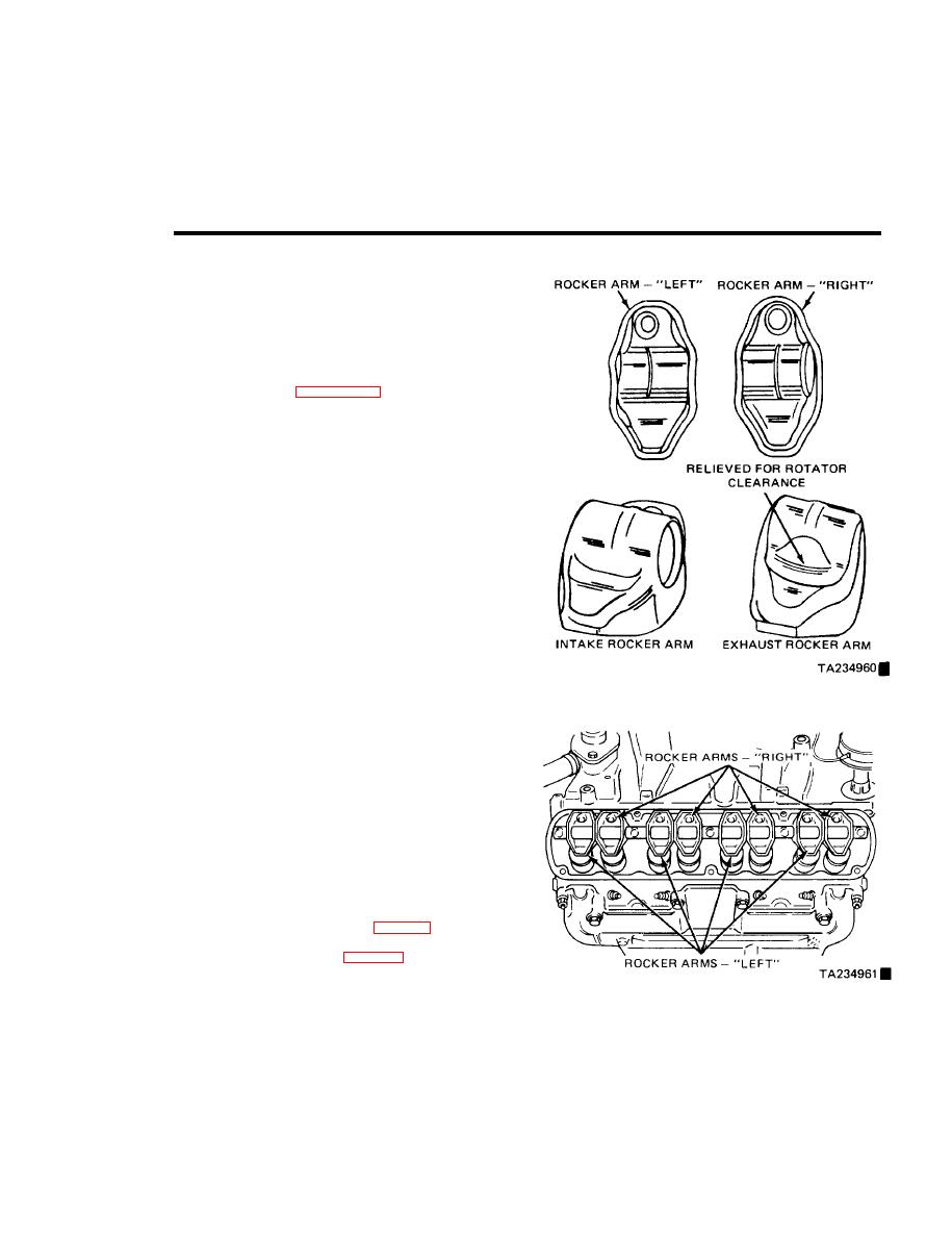
Figure 3-1. Intake and Exhaust Rocker Arm Identification.
(2) Remove the five rocker shaft attaching bolts.
(3) Lift the rocker shaft off the head,
(4) Slide the rockers off the shaft. Lay them on a
work bench in the same order that they are installed on the
shaft.
NOTE
When you reassemble the rocker shaft
assembly, the rockers must be installed in
the same position they were in before
disassembly.
b. Assembly and Installation. Rocker arms are reassem-
bled on the shaft in groups of two. See figure 3-1 for identi-
fication of left-side and right-side rocker arms. Position the
Figure 3-2. Proper Rocker Arm Locution on Shaft.
Change 7
3-1


