
TM 9-2320-266-34
a. General Information. After completing a major over-
haul, coat the threads of the wormshaft adjuster, the side
cover bolts, and the sector shaft lash adjuster bolt sparingly
with a non-hardening oil resistant sealing compound. This
will help keep the lubricant from leaking from the steering
gear assembly. After installing new sector shaft and worm-
shaft seals, and assuring that the sector shaft bushings and
wormshaft bearing cups in the gear housing are satisfactory,
continue with the assembly procedure.
b. Assembly Procedure.
(1) Hold the gear housing in a vise by clamping a
mounting lug in the vise, with the wormshaft bore in a hori-
zontal position and the side cover opening facing upward.
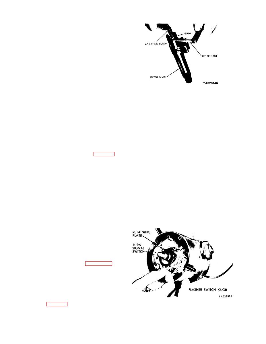
Figure 21-8. Checking Lash Adjuster End Clearance.
(2) With the upper ball bearing on the wormshaft,
install the wormshaft and nut assembly into the housing,
positioning the wormshaft through the upper ball bearing
(7) Rotate the wormshaft to bring the ball nut to the
cup and seal.
center of its travel.
(3) Assemble the ball bearing and seal into the worm-
(8) Install the sector shaft assembly, including the
shaft adjuster plug. Press the retainer into position.
adjuster screw and shim, into the housing. Engage the
(4) Place the adjuster and locknut into position,
center tooth of the sector with the tooth space in the
guiding the wormshaft into the bearing. Tighten the
center of the ball nut.
adjuster until very little wormshaft end play remains.
(9) Pack more lubricant into the housing and make
(5) Place the sector shaft lash adjuster screw, with
sure that the side cover bushing bore is lubricated.
shim, in the slotted end of the sector shaft. With the
(10) Position the side cover gasket.
adjuster screw positioned in the slot at the end of the sector
shaft, check the end clearance of the screw (figure 21-8).
(11) Install the side cover. Reach through the side
Hold the clearance to 0.002 inch or less. A selection of
cover adjusting screw hole with a screwdriver and turn the
four shims having thicknesses of 0.063, 0.065, 0.067, and
lash adjuster screw counterclockwise until it bottoms. Then
0.069 inch are available.
turn in the opposite direction one half turn. Start the lock-
nut and tighten finger-tight.
(6) Lubricate the steering gear with GAA grease.
Turn the wormshaft until the ball nut is at the end of its
(12) Install the side cover bolts and tighten to 30 ft-lbs.
travel. Pack as much lubricant into the housing as possible,
(13) Adjust the steering gear.
without losing it out of the sector shaft opening. Turn the
(14) Tighten the wormshaft adjuster locknut and
wormshaft until the ball nut is at its other extreme. Pack
sector shaft adjuster locknut to 85 ft-lbs.
as much lubricant into the housing as possible.
Section Il. REPAIR OF THE STEERING COLUMN ASSEMBLY
21-5. Steering Column Assembly.
a General. The following procedures are for use in
repairing the steering column after it has been removed from
the truck. Steering column removal and installation is
covered in paragraph 7-20. Procedures for removing and
installing the ignition switch and housing while the steering
column is still in the truck are given in paragraph 10-3.
b. Disassembling the Column.
(1) Clamp the column assembly in a vise.
(2) Drive out the gear selector lever pin, then remove
the lever and spring from the housing.
(3) Remove the turn signal switch and upper bearing
retainer screws. Remove the retainer and lift the switch up
Figure 21-9. Retainer and Turn Signal Switch
out of the way (figure 21-9). Remove the turn signal lever.
21-4
