TM 9-2320-266-34
k. Position the rotor and the drive end shield assembly
terminal junction block studs. Install the screws through
over the stator and the rectifier end shield assembly. Aline
the end shield and into the negative heat sink (figure 14-18).
the bolt holes in the stator, rectifier plate, and drive end
shields.
l. Compress the stator and both end shields manually
and install the bolts and washers. Tighten the bolts evenly.
m. Install the field brushes in the insulated holders.
Position the vertical and horizontal field brushes in the
proper location in the rectifier end shield.
n. Place the insulating washer on each field brush
terminal and install the Iockwashers and attaching screws.
Be sure that the brushes are not grounded. Tighten the
attaching screws.
o. Rotate the pulley slowly by hand to be sure that the
rotor fan blades do not hit the stator winding leads.
output (see TM 9-2320-266-20 for procedures). Output
current must be at least 47 amps.
14-6. Test Stand Operation.
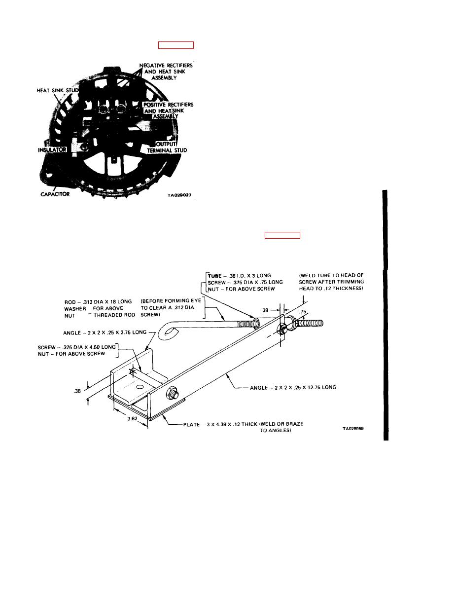
Figure 14-18. Capacitor and lnsulator Installed.
the operating procedures for the test stand.
necessary to make an adapter. Instructions for making the
install the winding terminals on the terminal block. Press
adapter are shown in figure 14-19.
the stator pins into the end shield and install and tighten
the winding terminal nuts. Route the leads so that they
cannot contact the rotor or the sharp edge of the negative
heat sink.
Figure 14-19. Test Stand Mounting Adapter.
Change 2
14-6


