TM 9-2320-266-34
CHAPTER 14
REPAIR OF THE ALTERNATOR
14-1. Rotor Field Coil Current Draw Test.
a. Connect a jumper wire between one field terminal of
Do not burr the laminated stator or the
the alternator and the positive terminal of a fully charged
end shield.
battery. Connect a test ammeter positive lead to the other
field terminal of the alternator. The negative ammeter lead
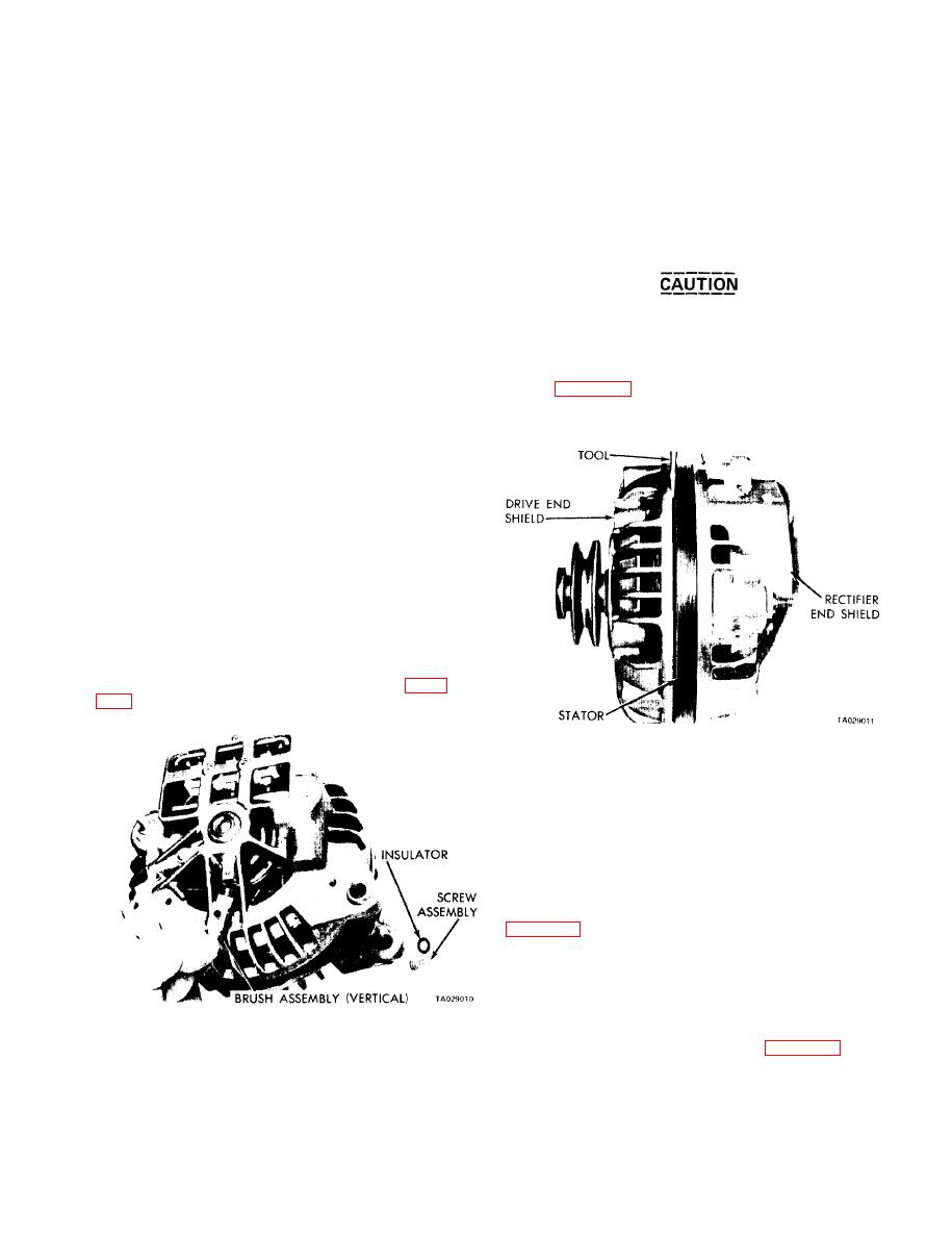
(2) Remove the through bolts and pry between the
goes to the battery negative terminal.
stator and the drive end shield with the blade of a screw-
driver (figure 14-2). Carefully separate the drive end shield,
pulley, and rotor assembly from the stator and rectifier end
the ammeter reading. Field coil draw should be 2.5 amps to
shield assembly.
3.7 amps at 12V.
c. A low rotor coil draw is an indication of high
resistance in the field coil circuit (brushes, slip rings, or
rotor coil). A higher rotor coil draw indicates a possible
shorted rotor coil or grounded rotor. No reading indicates
an open rotor or defective brushes.
14-2. Disassembling the Alternator and Separating
the Alternator and Shields.
a. General. Remove the brush assemblies before
separating the end shields to prevent damage. The field
brushes are positioned against the slip rings of the rotor.
b. Disassembly Procedure.
(1) Remove the brush screws and insulating washers
and lift the brush assemblies from the end shield (figure
Figure 14-2. Separating Drive End Shield from Stator.
14-3. Component Tests.
a. Testing the Rectifiers. There are two rectifier plates
in the rectifier end shield. One is positive and the other is
negative in polarity. The following test procedure applies
to both plates.
(1) Remove the nuts from the terminal block studs
that secure the stator windings. Remove the nuts securing
the positive and negative rectifier straps to the block. See
(2) Lift off the stator winding terminals and carefully
pry the stator assembly from the end shield.
the multimeter. Contact the heat sink of a rectifier plate
Figure 14-1. Removing Field Brushes.
with one test probe; contact the strap on top of the indi-
vidual rectifier with the other test probe (figure 14-4).
14-1


