TM 9-2320-266-34
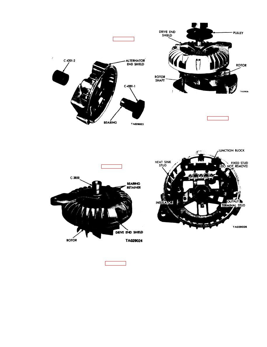
b. Position the rectifier end shield bearing on the base
of tool C-4201. Place the alternator end shield on top of
the bearing so that it is properly alined. With the top part
of tool C-4201 placed on the end shield, press it into place
until it bottoms against the alternator (figure 14-14). New
bearings are prelubricated; additional lubrication is not
required.
Figure 14-16. Installing Pulley.
f. If removed, install the output terminal stud and the
insulator through the end shield. Be sure the mica insula-
tors are in place and undamaged (figure 14-17).
g. Install the positive heat sink assembly over the studs;
guide the rectifier straps over the studs on the terminal
Figure 14-14. Installing Rectifier End Shield Bearing.
block.
c. Insert the drive cnd bearing in the drive end shield
and install the bearing retainer plate to hold the bearing
in place,
d. Position the bearing and drive end shield on the rotor
shaft and, while supporting the base of the rotor shaft, press
the bearing end shield into position on the rotor shaft with
an arbor press and tool C-3858 (figure 14-15).
Figure 14-17. Output Terminal Stud and
Insulators Installed.
h. Install the capacitor terminal over the capacitor end
Figure 14-15. Installing Drive End Shield Bearing,
stud. Install the capacitor shoulder insulator. Ground the
e. Install the pulley on the rotor shaft, The shaft of the
capacitor bracket to the end shield with a metal screw.
rotor must be supported in a manner so all pressing force is
install and tighten the positive heat sink nut and the lock-
on the pulley hub and rotor shaft (figure 14-16). Press the
washer assemblies
pulley on the rotor shaft until the pulley contacts the inner
cup of the drive and bearing.
into place in the end shield. Position the straps on the
14-5


