TM 9-2320-266-34
(2) To install a new negative plate, reverse the above
procedure.
b. Replacing Positive Rectifier Plates.
(1) Remove the two nut and washer assemblies
securing the rectifier plate to the insulated terminals in the
rectifier end shield. Remove the screw grounding the
capacitor to the case. Lift out the insulated washer, the
capacitor, and the positive rectifier plate,
(2) To install a new positive plate, reverse the above
procedure.
c. Removing the Pulley and Bearing.
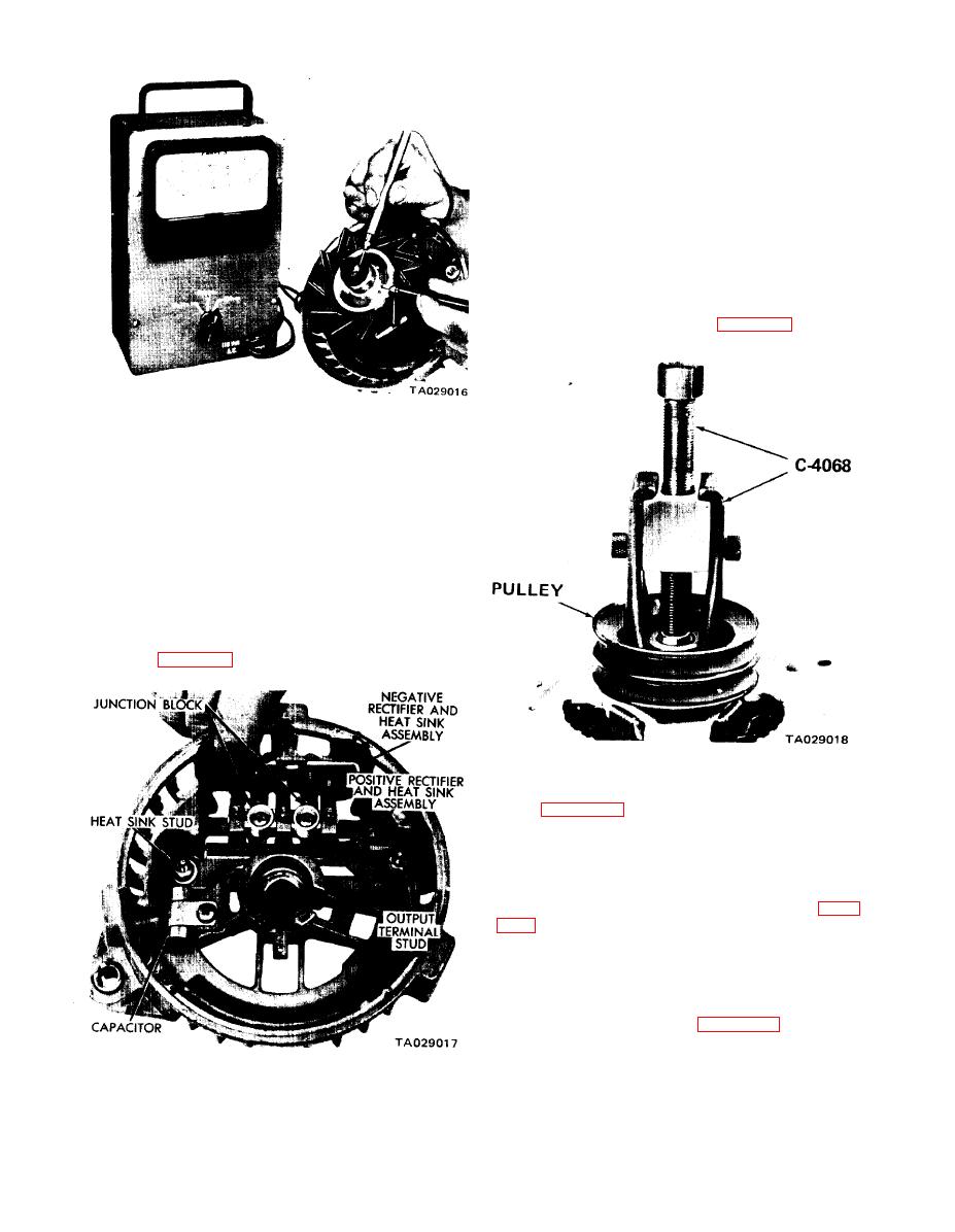
(1) The pulley is pressed on the rotor shaft. Remove
the pulley with puller tool C-4068 (figure 14-9).
Figure 14-7. Rotor Test.
(2) Test for open. To check for an open field coil,
connect an ohmmeter to the slip rings. The ohmmeter
reading should be between 3 and 4 ohms on the rotor coils.
(3) Test for short. To check for a shorted field coil,
connect an ohmmeter to the two slip rings. If the reading
is below 3 ohms, replace the field coil.
14-4. Replacing the Rectifiers, Pulley, and Bearing.
a. Replacing Negative Rectifier Plates.
(1) Loosen the four hexagon-head screws that secure
the rectifier plate to the rectifier end shield. Completely
remove the two outer screws and lift the plate out of the
end shield (figure 14-8).
Figure 14-9. Removing Pulley.
(2) Pry the drive end bearing retainer from the end
shield (figure 14-10).
(3) Support the end shield and tap the rotor shaft
with a plastic hammer to separate the rotor from the end
shield.
(4) The drive end ball bearing is pressed on the rotor
shaft. Remove the bearing with puller tool C-4068 (figure
shield is a press fit. If it is necessary to remove the rectifier
end frame needle bearing, protect the end shield by
supporting the shield with tool C-3925 when pressing the
bearing out with tool C-3770-A (figure 14-12).
Figure 14-8. Removing Negative Rectifier Plate.
14-3


