TM 9-2320-266-34
13-3. Removing the Pickup Coil.
a. Remove the reluctor by prying it up from the bottom
with two pry bars or screwdrivers.
Be careful not to damage the reluctor teeth
b. Remove the two screws attaching the vacuum control
unit to the distributor housing.
c. Disconnect the vacuum control arm from the pickup
coil and plate assembly and remove the control unit.
d. Remove the pickup coil leads from the distributor
housing.
e. Remove the two screws attaching the lower plate to
the distributor housing.
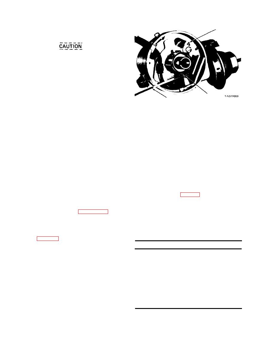
Figure 13-2. Air Gap Adjustment.
f. Lift the pickup coil and plate assembly out of the
housing.
g. Separate the pickup coil and plate assembly from the
13-6. Centrifugal Advance Curve.
lower plate by depressing the retainer clip in the underside
Mount the distributor assembly without the cap and rotor
of the lower plate and moving it away from the attaching
in a stroboscope-type distributor tester. It is important to
stud. The pickup coil is not removable from the plate.
connect the appropriate adapter for checking an electronic-
13-4. Installing the Pickup Coil.
type distributor to the distributor stand and to follow the
instructions for its use carefully. Test as follows:
a. Place a small amount of distributor cam lubricant on
the upper plate support pins located on the lower plate.
a. Turn the selector switch to the eight cylinder
position and turn the motor switch clockwise.
b. Position the upper plate on the lower plate. Install the
retainer clip and depress and lock into place.
b. Regulate the tester speed control to rotate the distrib-
utor at 200 rpm.
c. Position the lower plate, the upper plate, and the pick-
up coil assembly in the distributor housing. Install the
c. Aline the "O" of the distributor tester degree with any
mounting screws and tighten them securely.
of the arrow flashes.
d. Attach the vacuum control arm to the upper plate.
d. Adjust the tester speed control to operate the distribu-
Position the control into place on the distributor housing.
tor at speeds called for in table 13-1. The arrow flashes must
Install the mounting screws and tighten them securely.
be opposite the tester degree ring to determine the degree of
advance.
e. Install the pickup coil leads to the distributor housing.
e. If advance is not according to specifications, replace
the distributor shaft assembly (the shaft, reluctor sleeve, and
correct installation procedures.
governor weights make up a complete assembly).
13-5. Air Gap Adjustment.
Table 13-1. Distributor Test Points
Refer to figure 13-2.
a. Position a reluctor tooth directly in line with the pick-
Part number
3755201
up coil tooth.
Rotation . . . . . . . . Clockwise
b. Loosen the pickup coil hold-down screw.
Firing order. . . . . . . . 1-8-4-3-6-5-7-2
c. Adjust the air gap to 0.008 inch, using a non-magnetic
Centrifugal advance . . . . . 0.5 to 3.0 @ 550
feeler gage (tool C-4229).
2.5 to 5.0 @ 700
(degrees at
d. Tighten the hold-down screw.
11.5 to 14.0 @ 2150
distributor rpm)
e. Recheck the air gap with a 0.010 feeler gage. A 0.010
Vacuum advance . . . . 0.5 to 2.5 @ 10 in
feeler gage should not fit into the air gap.
7.5 to 9.5 @ 15 in
(degrees at inches
f. Apply vacuum to the vacuum unit and rotate the gov-
of mercury)
ernor shaft. The pickup pole should not hit the reluctor
Shaft side play. . . . . . . Not to exceed 0.006 in
teeth. If hitting occurs on the reluctor, the distributor shaft
Shaft end play . . . . . . . 0.003 to 0.017 in
is bent. Replace the shaft assembly.
13-2


