TM 9-2320-289-20
10-14. HEATER CONTROL REPLACEMENT (Con’t).
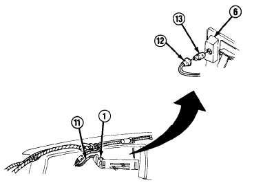
3.
Disconnect wiring harness (11) from
blower switch (1). Disconnect wiring
harness lead (12) and indicator bulb
(13) from heater control assembly
(6) .
Remove
heater
control
assembly.
b.
INSTALLATION
1.
Connect indicator bulb (13) and wiring harness lead (12) to heater control assembly (6).
Connect wiring harness (11) to blower switch (1).
2.
Connect temperature cable (9) to lower control arm (8) and heater control base (2), and
install nut (10). Connect defroster cable (3) to upper control arm (5) and heater control base,
and install nut (4).
3.
Install heater control assembly (6) with 4 screws (7).
FOLLOW-ON TASKS:
• Install instrument cluster plate, (See paragraph 4-7)
TA49966
10-45/(10-46 blank)