TM 9-2320-289-20
5-6.
TRANSFER CASE LINKAGE AND CONTROL LEVER ASSEMBLY
MAINTENANCE (ALL EXCEPT M1028A1 AND M1031) (Con’t).
c.
ADJUSTMENT
1.
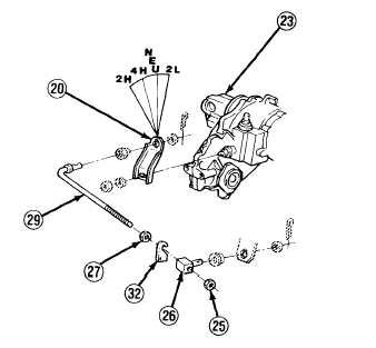
At transfer case (23), place operating lever (20) into “4H” position.
2.
Inside truck, place transfer case control lever into “4H” position.
NOTE
A 0.200 in. (0.51 cm) gage (32) must be made for use in steps 3 and 4. It
may be made from any material and shaped as illustrated.
3.
Hang gage (32) over rod (29) behind swivel (26). Run nut (27) against gage with shifter
against “4H” stop.
4.
Remove gage (32) and push swivel (26) rearward against nut (27).
5.
Run nut (25) against swivel (26) and tighten.
FOLLOW-ON TASKS:
• If removed, install transfer case bezel and boot. (See paragraph 5-4)
• Check operation of control lever and linkage.
TA49642
5-14