TM 9-2320-289-20
4-8.
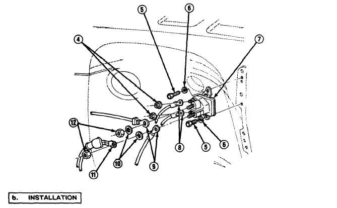
GLOW PLUG RELAY AND MODULE REPLACEMENT (Con’t).
4.
Remove 2 nuts (4) and leads (8).
5.
Remove 2 bolts (5) and Iockwashers (6). Remove glow plug relay (7). Discard Iockwashers.
NOTE
If installing relay (7), perform steps 1-3.
If installing module (2), perform steps 4 and 5.
1.
Install glow plug relay (7) with 2 new Iockwashers (6) and bolts (5).
2.
Install leads (8) with 2 nuts (4).
3.
Install 2 leads (9), 2 washers (10), lead (11), and 2 nuts (12).
4.
Install glow plug module (2) inside glow plug module housing (1) and install end cap (3).
5.
Install glow plug module housing (1) to bracket under instrument panel to left of steering
column.
FOLLOW-ON TASKS:
Connect both battery negative cables if disconnected. (See paragraph 4-38)
Check operation of glow plugs.
TA49866
4-25